 Royal Enfield Interceptor 650 - Service manual > Injector, TPS, MAPS, ISC Connections
Injector, Throttle Position Sensor (TPS), Manifold Absolute Pressure (MAP) Sensor and Idle Speed Controller (ISC) Connections
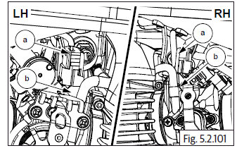
- Connect the LH and RH injector connectors (a) located on throttle body (b).
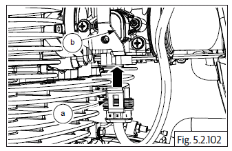
- Connect TPS connector (a) to sensor (b) at bottom of throttle body.
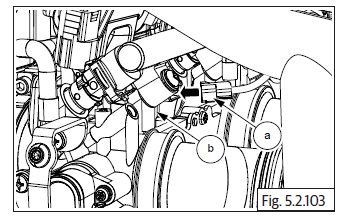
- Connect idle speed sensor connector (a) on throttle body (b).
- Connect purge valve hoses (a) to the inlet pipes on the top of the throttle body.
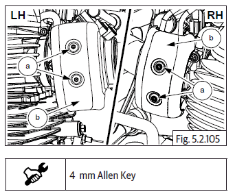
Throttle Body Covers on LH and RH
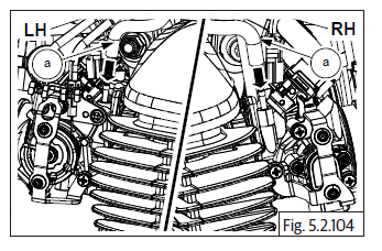
- Locate throttle body covers (b) on both LH and RH of throttle body.
- Insert and tighten 2 Nos. Hex Allen bolts (M5) (a) into LH throttle body cover (b).
- Insert and tighten 2 Nos. Hex Allen bolts (M5) (a) into RH throttle body cover (b).
- Position ABS modulator with bracket on frame and tighten with bolts.
- Assemble the following parts:
- Horn and electrical connections.
- Connect HT cable.
- Fuel tank.
- Side panels LH.
- Rider seat assembly.
- Assemble RH side panel.
Spark Plugs
- Locate and tighten spark plug (a) to RH cylinder head.
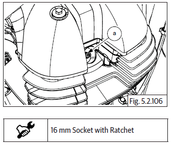
- Repeat the procedure to assemble LH spark plug.
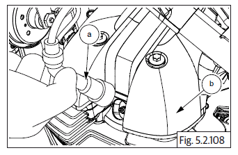
Spark Plug Suppressor Caps
Spark Plug Suppressor Caps on LH and RH Cylinder Heads
- Locate spark plug suppressor cap (a) on spark plug in LH cylinder head (b).
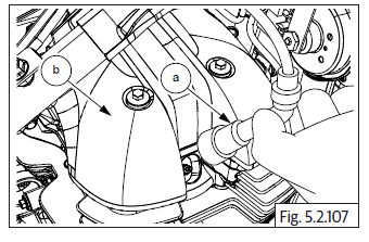
- Locate spark plug suppressor cap (a) on spark plug in RH cylinder head (b).
Star Index
- Locate and tighten 2 Nos. Hex head bolts (M6) (a) on selector fork shaft stopper plate.
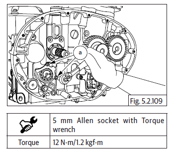
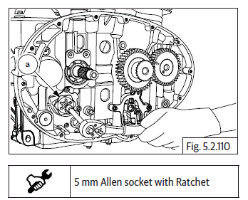
- Locate and tighten Hex socket head stepped bolt (M6) (a) on gear shift cam drum.
Star Index Stopper
- Locate spring and stopper plate support (a) on RH lower crankcase and assemble Hex head flange bolt (M6) (b).
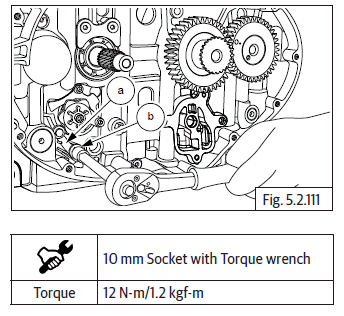
NOTE
- Handle stopper plate tension spring carefully else it may damage supporting components.
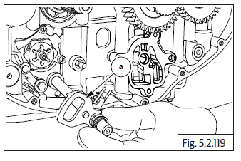
Shifter Selector Shaft Assembly
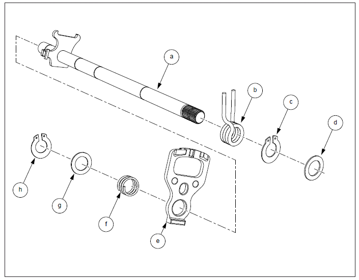
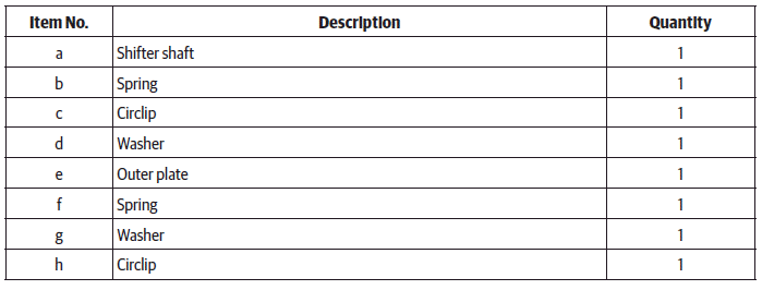
Shifter Selector Shaft
- Assemble inner spring (a) from the longer side of shifter shaft (b).
- Ensure the legs of the spring are correctly located in the plate on the shifter shaft.
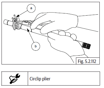
- Assemble inner circlip (a) on longer end of shifter shaft (b). Ensure it is properly seated on shifter shaft groove near the spring.
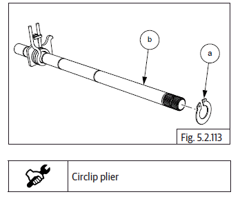
- Assemble 1 st inner washer (a) from the longer end of shifter shaft (b).
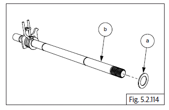
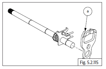
- Assemble outer plate (a) from smaller end of shifter shaft with its projection facing towards the longer end of the shaft.
- Ensure the peg on the shifter shaft is located correctly in the hole on the outer plate (a).
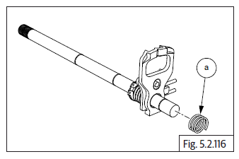
- Assemble outer spring (a) from smaller end of shifter shaft.
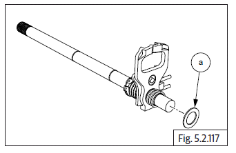
- Assemble outer washer (a) from the smaller end of shifter shaft.
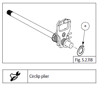
- Assemble outer circlip (a) from smaller end of shifter shaft.
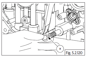
- Insert longer end of the shifter shaft (a) into the hole in the lower crankcase from the RH side.
- Ensure the shifter plate is correctly seated over the star index.
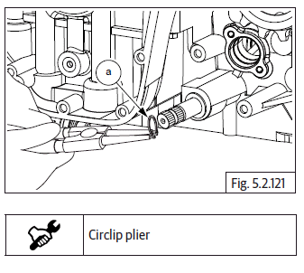
- Assemble washer (a) on the shifter shaft on the LH side.
- Assemble circlip (a) on the shifter shaft at the LH side and ensure it is correctly seated and locked in the groove on the shifter shaft.
See also:
 Royal Enfield Interceptor 650 - Service manual > Reed Valves
NOTE The reed valve has a rounded edge in one of the corners this should be aligned to the rounded edge in the housing during assembly. Locate reed valves LH & RH (a) in the housings duly ensuring it is seated properly and correctly. Assemble new "O" rings (b) on either ends of the connection tube and locate the reed valves housings LH & RH on the connection tube duly ensuring the connection tube is fully inserted into the housings. Locate reed valves on cylinder head front side with the hose (a) pointing upwards and ensure the mounting holes are aligned. Locate 2 each Hex socket head bolts (M6) (a) on the LH and RH reed valves and tighten evenly to specified torque.
Royal Enfield Interceptor 650 - Service manual > Oil Pump
Locate oil pump mounting point below crankshaft gear in RH crankcase. Assemble 4 Nos. Hex flange head bolts (M6) (a) on oil pump (b) and tighten bolts to specified torque. Locate and fit oil pump drive chain (a) on crankshaft gear (b) and sprocket on oil pump. Locate Hex flange head bolt (M6) (a) on oil pump. DO NOT TIGHTEN FULLY. Tighten the bolt to specified torque.
 Rider's Manual BMW R 1250 GS GSA
 Owner's Manual Harley-Davidson Sportster XL1200X Forty-Eight
 Owner's Manual Honda CBR650R
 Service manual Honda CBR650
 Owner's Manual Honda PCX125
 Owner's Manual Kawasaki Z1000SX
 Service manual Kawasaki Z1000SX
 Owner's Manual Lexmoto Echo
 Owner's Manual Royal Enfield Interceptor 650
 Service manual Royal Enfield Interceptor 650
 Owner's Manual Yamaha MT-07