 Royal Enfield Interceptor 650 - Service manual > Reed Valves
NOTE
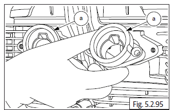
- The reed valve has a rounded edge in one of the corners this should be aligned to the rounded edge in the housing during assembly.
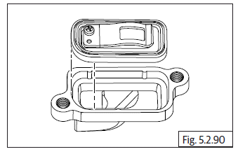
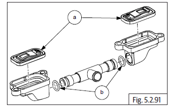
- Locate reed valves LH & RH (a) in the housings duly ensuring it is seated properly and correctly.
- Assemble new "O" rings (b) on either ends of the connection tube and locate the reed valves housings LH & RH on the connection tube duly ensuring the connection tube is fully inserted into the housings.
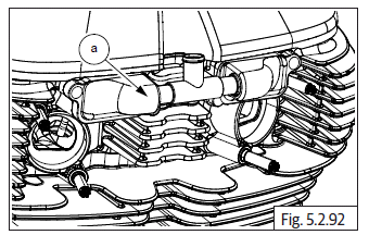
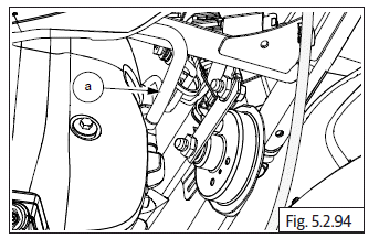
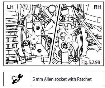
- Locate reed valves on cylinder head front side with the hose (a) pointing upwards and ensure the mounting holes are aligned.
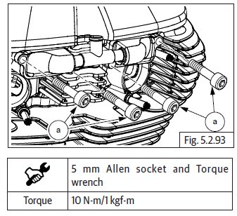
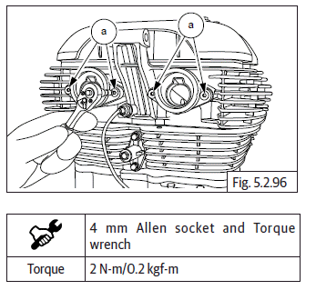
- Locate 2 each Hex socket head bolts (M6) (a) on the LH and RH reed valves and tighten evenly to specified torque.
Reed Valve Connection
- Connect the hose (a) to the reed valve tube.
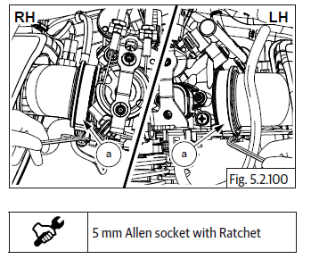
Inlet Manifold Rubber Flanges LH & RH
- Locate the 2 Nos. inlet manifold rubber flanges (a) on the cylinder heads, duly ensuring the "cut away" in the manifolds are matching with the "cut away" in the cylinder head.
- Locate and tighten 2 each countersunk socket head bolts (M5) (a) on the inlet manifold rubber flanges LH & RH.
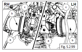
Throttle Body
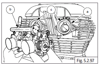
- Ensure clips (a) are in position on inlet manifolds LH and RH and loosened sufficiently.
- Locate throttle body (b) on the inlet manifold (c) and ensure it is properly seated on both LH and RH inlet manifolds fully.
- Tighten both clips screws (M6) (a) sufficiently over inlet manifolds LH & RH.
Air Filter Hoses On Throttle Body
- Ensure clips (a) are in position on air filter hoses and loosened sufficiently.
- Locate air filter hoses (b) on throttle body (c) and ensure they are properly seated on the throttle body.
- Tighten both clips screws (M6) (a) sufficiently over the air filter hoses.
Throttle Cables
- Assemble throttle cables on throttle body.
See also:
 Royal Enfield Interceptor 650 - Service manual > Tappet Clearance Adjustment
Tappet Clearance Cylinder Head LH Ensure "L" mark on camshaft (a) is aligned to cylinder head. Ensure the flat edge of the special tool (a) is correctly located in the slot on the camshaft on RH side AND the tool is resting correctly on the cylinder head. Gently rotate crankshaft to ensure proper seating of the tool in the camshaft slot and cylinder head. Loosen tappet adjuster screw locknut (a) with tappet adjusting tool and ensure locknut is sufficiently loose. Insert a screwdriver into the tappet adjusting tool (b) and ensure it is seated correctly on the adjuster screw (a). Locate feeler strip (a) between adjuster screw and valve stem as per thickness mentioned below. Gently pull out feeler strip (a) and check if it comes out freely OR with resistance. In case feeler strip comes out freely the adjuster screw has to be tightened. In case feeler strip movement is hard, the adjuster screw must be loosened. Tighten/loosen adjuster screw using screw driver, while simultaneously checking correct and smooth movement of feeler strip. Ensure tappet adjusting tool (a) does not rotate while adjusting the screw. After setting correct gap, remove feeler strip, hold screw driver firmly such that the setting DOES NOT gets disturbed and gently lock the lock nut against rocker arm using special tool (a). Repeat above steps to adjust the other tappet in cylinder head LH.
Royal Enfield Interceptor 650 - Service manual > Injector, TPS, MAPS, ISC Connections
Injector, Throttle Position Sensor (TPS), Manifold Absolute Pressure (MAP) Sensor and Idle Speed Controller (ISC) Connections Connect the LH and RH injector connectors (a) located on throttle body (b). Connect TPS connector (a) to sensor (b) at bottom of throttle body. Connect idle speed sensor connector (a) on throttle body (b). Connect purge valve hoses (a) to the inlet pipes on the top of the throttle body.
 Rider's Manual BMW R 1250 GS GSA
 Owner's Manual Harley-Davidson Sportster XL1200X Forty-Eight
 Owner's Manual Honda CBR650R
 Service manual Honda CBR650
 Owner's Manual Honda PCX125
 Owner's Manual Kawasaki Z1000SX
 Service manual Kawasaki Z1000SX
 Owner's Manual Lexmoto Echo
 Owner's Manual Royal Enfield Interceptor 650
 Service manual Royal Enfield Interceptor 650
 Owner's Manual Yamaha MT-07