 Royal Enfield Interceptor 650 - Service manual > Tappet Clearance Adjustment
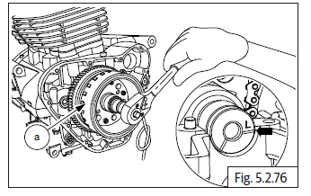
Tappet Clearance Cylinder Head LH
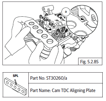
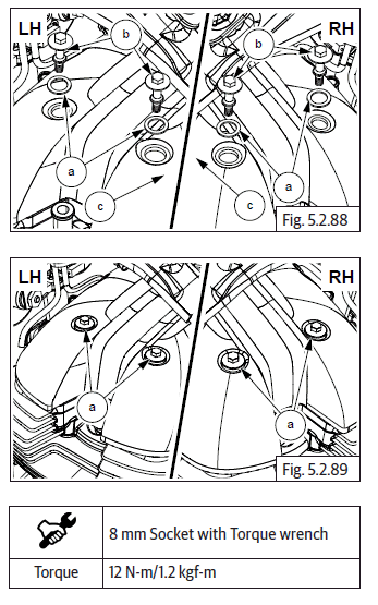
- Ensure "L" mark on camshaft (a) is aligned to cylinder head.
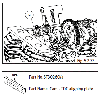
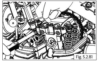
- Ensure the flat edge of the special tool (a) is correctly located in the slot on the camshaft on RH side AND the tool is resting correctly on the cylinder head.
- Gently rotate crankshaft to ensure proper seating of the tool in the camshaft slot and cylinder head.
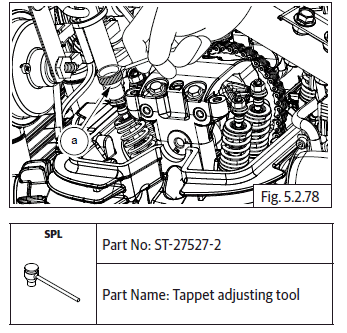
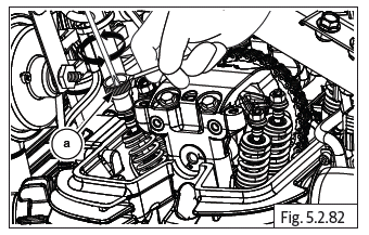
- Loosen tappet adjuster screw locknut (a) with tappet adjusting tool and ensure locknut is sufficiently loose.
- Insert a screwdriver into the tappet adjusting tool (b) and ensure it is seated correctly on the adjuster screw (a).
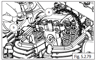
- Locate feeler strip (a) between adjuster screw and valve stem as per thickness mentioned below.
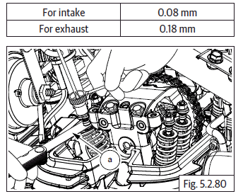
- Gently pull out feeler strip (a) and check if it comes out freely OR with resistance.
- In case feeler strip comes out freely the adjuster screw has to be tightened.
- In case feeler strip movement is hard, the adjuster screw must be loosened.
- Tighten/loosen adjuster screw using screw driver, while simultaneously checking correct and smooth movement of feeler strip.
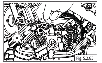
- Ensure tappet adjusting tool (a) does not rotate while adjusting the screw.
- After setting correct gap, remove feeler strip, hold screw driver firmly such that the setting DOES NOT gets disturbed and gently lock the lock nut against rocker arm using special tool (a).
- Repeat above steps to adjust the other tappet in cylinder head LH.
NOTE
- Reconfirm correctness of tappet clearances before final locking of lock nuts.
CAUTION Do not adjust tappets with less OR no clearance as it will result in poor compression, valve burn-out and wear-out of tappet adjuster foot.
Do not adjust tappet with high clearance as will result in noise and insufficient opening of the valves.
- Remove screw driver and both special tools after adjustment is complete.
Tappet Clearance Cylinder Head RH
- Ensure "R" mark on camshaft (a) is aligned to cylinder head.
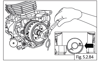
- Ensure the angular edge of the special tool (a) is correctly located in the slot on the camshaft on RH side AND the tool is resting correctly on the cylinder head.
- Gently rotate crankshaft to ensure proper seating of the tool in the camshaft slot and cylinder head.
- Adjust the tappets clearances as mentioned in tappets adjustment LH.
Cover Cylinder Head
NOTE
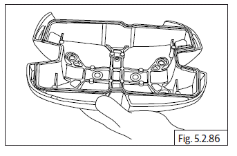
- Ensure the cover-cylinder head seating surface and gasket seating groove are clean.
- Locate new rubber gasket in the groove in cylinder head cover and ensure it is properly and evenly seated.
- Locate cylinder head cover (a) on cylinder head with its narrow slot facing towards the front of the engine.
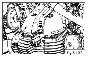
- Assemble new seal washers (a) on the 4 Nos. Hex flange head bolts (M5) (b).
- Locate the bolts on cylinder head cover (c) and tighten bolts to cylinder head evenly to specified torque.
See also:
 Royal Enfield Interceptor 650 - Service manual > Camshaft Sub Assembly
Hold the timing chain in stretched condition and gently rotate crankshaft clockwise to bring LH piston to TDC.
Royal Enfield Interceptor 650 - Service manual > Reed Valves
NOTE The reed valve has a rounded edge in one of the corners this should be aligned to the rounded edge in the housing during assembly. Locate reed valves LH & RH (a) in the housings duly ensuring it is seated properly and correctly. Assemble new "O" rings (b) on either ends of the connection tube and locate the reed valves housings LH & RH on the connection tube duly ensuring the connection tube is fully inserted into the housings. Locate reed valves on cylinder head front side with the hose (a) pointing upwards and ensure the mounting holes are aligned. Locate 2 each Hex socket head bolts (M6) (a) on the LH and RH reed valves and tighten evenly to specified torque.
 Rider's Manual BMW R 1250 GS GSA
 Owner's Manual Harley-Davidson Sportster XL1200X Forty-Eight
 Owner's Manual Honda CBR650R
 Service manual Honda CBR650
 Owner's Manual Honda PCX125
 Owner's Manual Kawasaki Z1000SX
 Service manual Kawasaki Z1000SX
 Owner's Manual Lexmoto Echo
 Owner's Manual Royal Enfield Interceptor 650
 Service manual Royal Enfield Interceptor 650
 Owner's Manual Yamaha MT-07