 Royal Enfield Interceptor 650 - Service manual > Camshaft Sub Assembly
- Hold the timing chain in stretched condition and gently rotate crankshaft clockwise to bring LH piston to TDC.
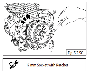
CAUTION DO NOT rotate crankshaft anti-clockwise.
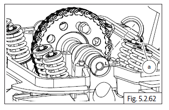
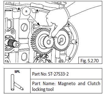
- Hold sprocket in position with one of the slotted holes facing on top.
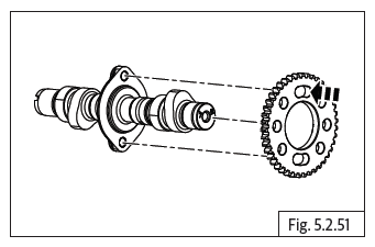
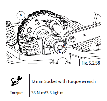
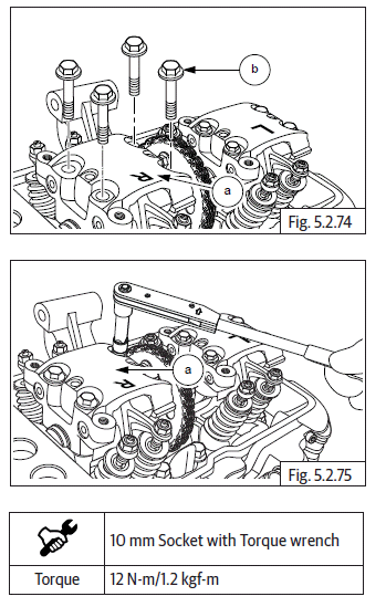
- Assemble cam chain (a) on sprocket and locate camshaft (b) into sprocket from the RH side.
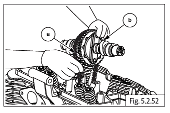
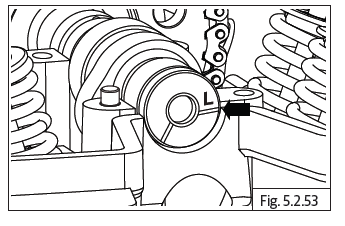
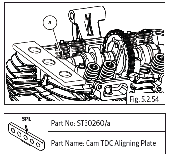
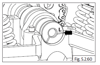
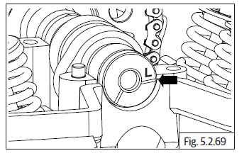
- Ensure reference mark "L" in the camshaft is aligned to the cylinder head on LH side.
-
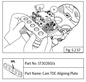
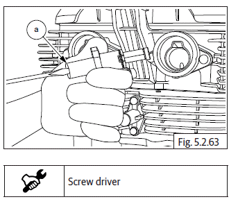
Ensure the flat edge of the special tool (a) is correctly located in the slot on the camshaft on RH side AND the tool is resting correctly on the cylinder head.
-
Gently rotate camshaft to ensure proper seating of the tool in the camshaft slot and cylinder head.
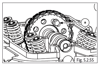
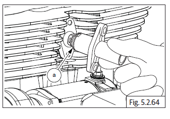
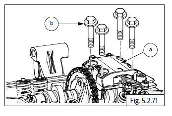
- Locate timing chain sprocket on camshaft with its mounting slot centralized to the threads in the camshaft.
- Locate and tighten Hex head bolt (M8) (a) sufficiently on timing chain sprocket. DO NOT TIGHTEN FULLY.
- Remove the special tool from the camshaft on RH side.
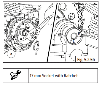
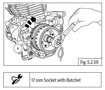
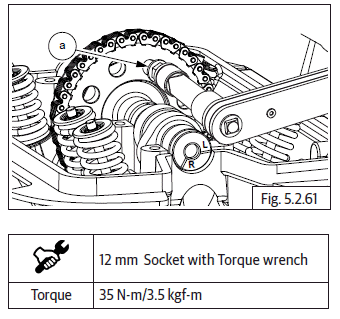
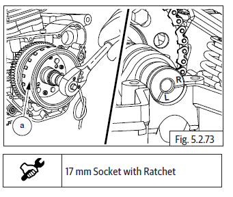
- Rotate magneto (a) till another slotted hole on cam chain sprocket is at top most position. Ensure reference mark "R" aligned to the cylinder head.
- Ensure the angular edge of the special tool (a) is correctly located in the slot on the camshaft on RH side AND the tool is resting correctly on the cylinder head.
- Gently rotate camshaft. If necessary, to ensure proper seating of the tool in the camshaft slot and cylinder head.
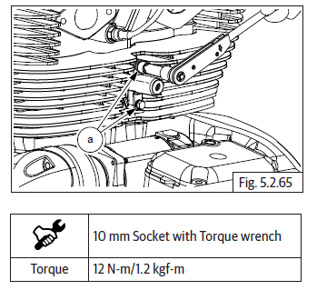
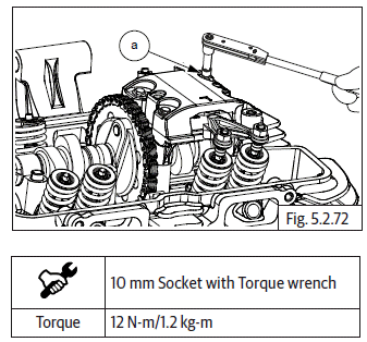
- Locate the other Hex head bolt (M8) (a) in the slotted hole on timing chain sprocket and tighten to specified torque.
- Remove the special tool from cylinder head on RH side.
- Rotate the magneto (a) clockwise till the first bolt is visible at top most position on cam chain sprocket.
- Ensure reference mark "L" in the camshaft is aligned to the cylinder head on LH side.
- Tighten Hex head bolt (M8) (a) to specified torque.
- Locate and fit "C" washer (a) on camshaft.
Timing Chain Tensioner
- Ensure center bolt is removed from timing chain tensioner.
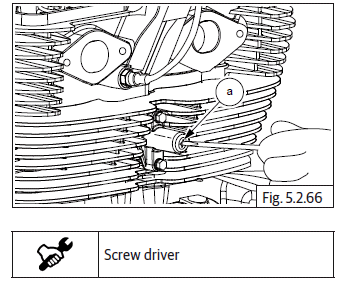
- Insert screw driver into timing chain tensioner adjuster (a) and loosen screw completely to release spring tension.
- Assemble new gasket on chain tensioner housing (a). Ensure the foot is fully retracted into chain tensioner and locate chain tensioner adjuster in cylinder barrel such that the longer side of the foot is facing towards cylinder barrel RH.
- Assemble 2 Nos. Hex flange head bolt (M6) (a) on chain tensioner adjuster and tighten to specified torque.
- Locate screw driver into chain tensioner adjuster (a) and tighten tensioner screw till it comes to a stop. DO NOT OVER TIGHTEN.
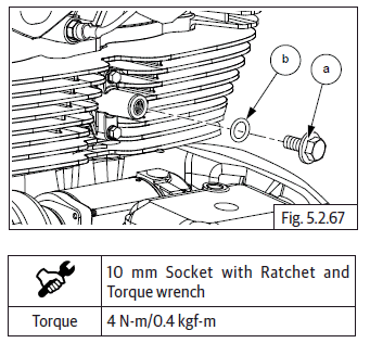
- Locate new O-ring (b) and, assemble Hex flange head bolt (M6) (a) on chain tensioner adjuster and tighten fully to specified torque.
Rocker Arms in Carriers LH and RH
Exhaust Rocker Arm in Carrier "L"
- Place the carrier (a) on a work table with the mark "L" facing upwards.
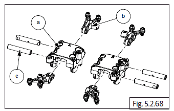
- Locate rocker arm (b) with the marking "EL" into carrier "L" duly
ensuring the following.
- The roller of the rocker arm is inserted from the side marked "L".
- The tappet adjustment screws are facing upwards.
- Ensure the holes are aligned and insert spindle with its small chamfer side in the carrier.
- Ensure cut away in spindle is correctly aligned to the carrier mounting hole.
- Align and insert the spindle (c) into rocker carrier and rocker arm.
Intake Rocker Arm in Carrier "L"
- Locate rocker arm with the marking "IL" into carrier "L" duly ensuring
the following.
- The roller of the rocker arm is inserted from the OPPOSITE side marked "L".
- The tappet adjustment screws are facing upwards.
- Ensure the holes are aligned and insert spindle with its small chamfer side in the carrier.
- Ensure cut away in spindle is correctly aligned to the carrier mounting hole.
- Align and insert the spindle (c) into rocker carrier and rocker arm.
- Repeat the above process to assemble rocker arm "ER" and "IR" into carrier "R".
Rocker Carrier on Cylinder Head LH
NOTE
- Ensure "L" mark on camshaft is aligned to cylinder head.
- Insert special tool (a) in crankcase RH to lock the crankshaft and prevent rotation.
- Ensure the tappet adjuster locknuts and adjusters are fully loosened on the intake and exhaust rocker arms.
- Assemble rocker carrier LH (a) on cylinder head LH such that tappet adjusters are above the inlet and exhaust valves.
- Assemble 4 Nos. Hex flange head bolts (M6) (b) on rocker carrier and tighten in a crisscross pattern to specified torque.
- Remove magneto and clutch locking tool from crankcase RH side.
Rocker Carrier on Cylinder Head RH
- Rotate magneto (a) clockwise and ensure reference mark "R" is aligned with cylinder head.
- Ensure the tappet adjuster locknuts and adjusters are fully loosened on the intake and exhaust rocker arms.
- Assemble rocker carrier RH (a) on cylinder head RH such that the tappet adjusters are above the inlet and exhaust valves.
- Assemble 4 Nos. Hex flange head bolts (M6) (b) on rocker carrier (a) and tighten in a crisscross pattern to specified torque.
See also:
 Royal Enfield Interceptor 650 - Service manual > Floating Chain Pad
Hold timing chain (a) suitably and insert chain pad (b) into cylinder barrel with the rubber track facing inside.
Royal Enfield Interceptor 650 - Service manual > Tappet Clearance Adjustment
Tappet Clearance Cylinder Head LH Ensure "L" mark on camshaft (a) is aligned to cylinder head. Ensure the flat edge of the special tool (a) is correctly located in the slot on the camshaft on RH side AND the tool is resting correctly on the cylinder head. Gently rotate crankshaft to ensure proper seating of the tool in the camshaft slot and cylinder head. Loosen tappet adjuster screw locknut (a) with tappet adjusting tool and ensure locknut is sufficiently loose. Insert a screwdriver into the tappet adjusting tool (b) and ensure it is seated correctly on the adjuster screw (a). Locate feeler strip (a) between adjuster screw and valve stem as per thickness mentioned below. Gently pull out feeler strip (a) and check if it comes out freely OR with resistance. In case feeler strip comes out freely the adjuster screw has to be tightened. In case feeler strip movement is hard, the adjuster screw must be loosened. Tighten/loosen adjuster screw using screw driver, while simultaneously checking correct and smooth movement of feeler strip. Ensure tappet adjusting tool (a) does not rotate while adjusting the screw. After setting correct gap, remove feeler strip, hold screw driver firmly such that the setting DOES NOT gets disturbed and gently lock the lock nut against rocker arm using special tool (a). Repeat above steps to adjust the other tappet in cylinder head LH.
 Rider's Manual BMW R 1250 GS GSA
 Owner's Manual Harley-Davidson Sportster XL1200X Forty-Eight
 Owner's Manual Honda CBR650R
 Service manual Honda CBR650
 Owner's Manual Honda PCX125
 Owner's Manual Kawasaki Z1000SX
 Service manual Kawasaki Z1000SX
 Owner's Manual Lexmoto Echo
 Owner's Manual Royal Enfield Interceptor 650
 Service manual Royal Enfield Interceptor 650
 Owner's Manual Yamaha MT-07