 Royal Enfield Interceptor 650 - Service manual > Floating Chain Pad
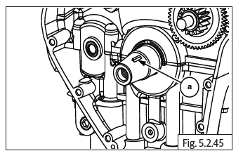
- Hold timing chain (a) suitably and insert chain pad (b) into cylinder barrel with the rubber track facing inside.
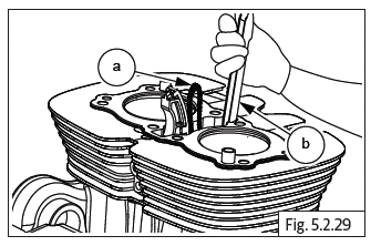
CAUTION Ensure floating chain pad seating correctly in the crankcase and free radial movement.
Components in Cylinder Head
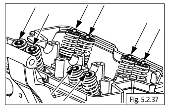
Valves and Springs
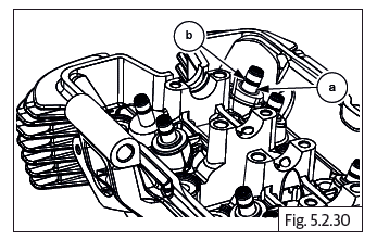
- Install 8 valve stem seals (b) on the 8 valve guides (a).
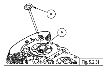
- Lubricate and insert the valves (a) into the valve guides inside cylinder head (b).
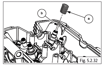
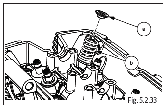
- Support the valve inside cylinder head and assemble valve spring (a) over valve stem (b) in the outer area of the cylinder head.
- Insert collar (a) above valve spring (b).
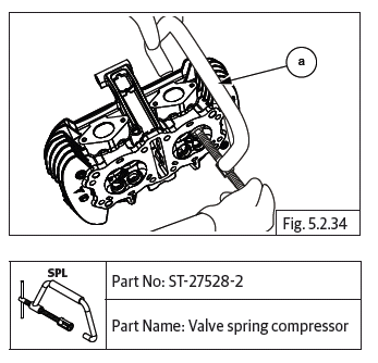
- Locate valve spring compressor special tool on the valve such that the threaded screw end of the tool is seated centrally on the valve inside the cylinder head and the other end is seated on the valve spring collar on the outer side of the cylinder head.
- Compress valve spring with special tool (a) by "hand tightening" the threaded screw of the special tool gently, till it locks against the valve.
CAUTION DO NOT overtighten the special tool as it will damage both the valve seating surface and the special tool.
- Locate two split cotters (a) on the collar with their tapered end facing inside and the flat edges seated against the valve stem top portion.
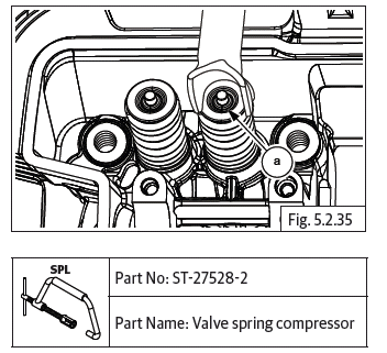
- Gently and slowly release valve spring compressor tool by unscrewing the threaded shaft, duly ensuring the valve cotters are locked in place on the valve stem and the tapered surfaces of the cotters are inside the valve spring collar.
- Remove valve spring compressor special tool (a) from the valve.
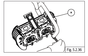
- Repeat the above process to install the other seven valves, springs, collars and cotters on the cylinder head.
Cylinder Head on Cylinder Barrel
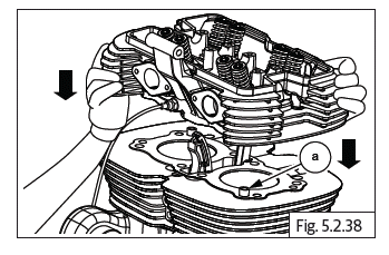
Cylinder Head Assembly on Cylinder Barrel
- Position cylinder head over the barrel such that the exhaust ports are facing towards the front and inlet ports are towards the rear of the engine.
- Ensure the 2 dowels (a) and cylinder head gasket are located on the cylinder barrel.
- Ensure the cam chain pads are positioned correctly and route the cam chain from the lower side of the cylinder head to the top.
- Support cam chain suitably to prevent it from falling into cylinder head.
CAUTION Cylinders bolts are pre-coated and hence should be used one time only. DO NOT reuse.
- Locate new 8 Nos. Hex flange head bolts (M10) (a) along with washers on the cylinder head.
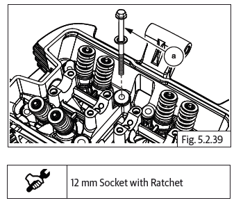
- Tighten the cylinder head bolts in a crisscross pattern to the initial 1 st torque values FIRST and then to the 2 nd torque values as specified below.
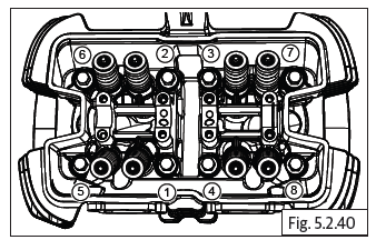
- Finally tighten each of the cylinder head bolts using an angular torque wrench, to the specified angular torque value given below and in the same crisscross pattern detailed above.
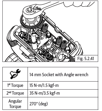
CAUTION Torque and angle should be as specified. Do not over-torque as it will damage the bolts.
Starter Clutch to Magneto Rotor
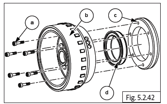
- Lubricate one-way clutch (d) and assemble into outer ring (c) with the collar seating in the groove in the outer ring.
- Position outer ring on magneto rotor such that the collar of the starter clutch is facing magneto rotor.
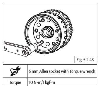
- Ensure mounting holes are aligned, insert 6 Nos. Hex socket head screws (M6) (a) into magneto rotor (b) and tighten outer ring (c) to rotor to specified torque.
Idle Gear in Crankcase LH
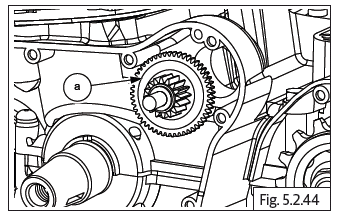
- Position idle gear (a) against crankcase with smaller gear facing outside and insert idle gear spindle into boss in crankcase.
Woodruff Key on Crankshaft
- Assemble woodruff key (a) on crankshaft and ensure it is facing upwards by rotating crankshaft.
Magneto Rotor on Crankshaft
- Position gear starter clutch with the collar facing outside.
- Insert gear starter clutch (a) into magneto rotor (b) and rotate anti-clockwise to lock the gear starter clutch into magneto rotor.
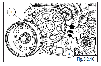
- Locate magneto rotor (a) on crankshaft duly ensuring the slot in the rotor is positioned correctly on woodruff key.
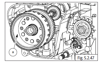
- Locate and assemble Hex flange bolt (M12) (a) with washer on magneto rotor and tighten bolt just sufficiently.
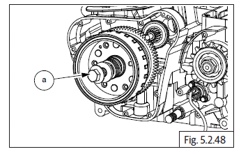
- In order to tighten magneto rotor bolt, Insert special tool (a) in crankcase RH to lock the crankshaft and prevent rotation.
- Ensure LH piston is at TDC on compression stroke, before locating special tool inside crankcase RH.
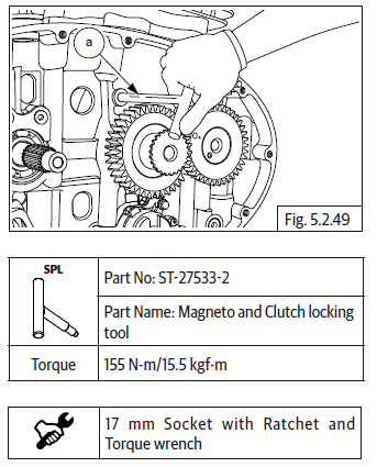
- Remove special tool from crankcase RH side after tightening magneto rotor bolt.
See also:
 Royal Enfield Interceptor 650 - Service manual > Piston Rings on Piston
NOTE Rings should be assembled with proper orientation (top marking should be always towards 1 st ring end gap should be 45º before "EX" mark on piston crown). Middle 2 nd ring end gap should be 180º from 1 st ring end gap. Oil ring 3 rd top rail end gap should be 180º from 2nd ring end gap (45º before "EX" on piston crown). Oil ring spacer end gap should be 45º before 3 rd ring top rail end gap (90º before "EX" on piston crown). Oil ring (3 rd ) bottom rail end gap should be 180º from 3 rd ring top rail end gap. One of the circlip should be assembled on the inner side of piston.
Royal Enfield Interceptor 650 - Service manual > Camshaft Sub Assembly
Hold the timing chain in stretched condition and gently rotate crankshaft clockwise to bring LH piston to TDC.
 Rider's Manual BMW R 1250 GS GSA
 Owner's Manual Harley-Davidson Sportster XL1200X Forty-Eight
 Owner's Manual Honda CBR650R
 Service manual Honda CBR650
 Owner's Manual Honda PCX125
 Owner's Manual Kawasaki Z1000SX
 Service manual Kawasaki Z1000SX
 Owner's Manual Lexmoto Echo
 Owner's Manual Royal Enfield Interceptor 650
 Service manual Royal Enfield Interceptor 650
 Owner's Manual Yamaha MT-07