 Royal Enfield Interceptor 650 - Service manual > Piston Rings on Piston
Engine / Components Assembly on Engine / Piston Rings on Piston
NOTE
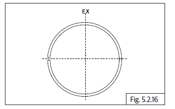
- Rings should be assembled with proper orientation (top marking should be always towards 1 st ring end gap should be 45º before "EX" mark on piston crown).
- Middle 2 nd ring end gap should be 180º from 1 st ring end gap.
- Oil ring 3 rd top rail end gap should be 180º from 2nd ring end gap (45º before "EX" on piston crown).
- Oil ring spacer end gap should be 45º before 3 rd ring top rail end gap (90º before "EX" on piston crown).
- Oil ring (3 rd ) bottom rail end gap should be 180º from 3 rd ring top rail end gap.
- One of the circlip should be assembled on the inner side of piston.
Piston Rings
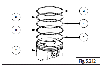
- Top ring
- Middle ring
- Oil ring top rail
- Oil ring spacer
- Oil ring bottom rail
- Piston
Orientation Pattern
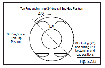
- Top ring (1 st ) and oil ring (3 rd ) top rail end gap positions.
- Middle (2 nd ) ring and oil ring (3 rd ) bottom rail end gap positions.
- Oil ring spacer end gap position.
Pistons on Connecting Rods
- Ensure circlip is assembled on the inner side of the piston LH.
- Ensure piston rings are assembled correctly on the piston.
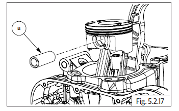
- Locate piston LH on the connecting rod LH with the marking "EX" on the piston crown is towards the front.
- Ensure gudgeon pin mounting holes on piston and connecting rod are aligned and insert gudgeon pin (a) into piston from the outside, till it stops against the circlip on the inner side of the piston.
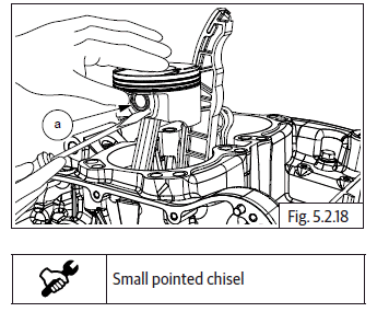
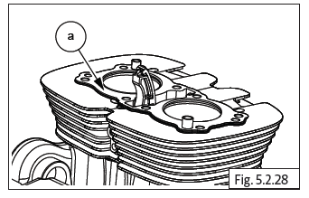
- Locate the other circlip (a) in the groove in piston and ensure it is correctly and properly seated inside the groove.
- Repeat above procedure to assemble piston RH on the connecting rod RH.
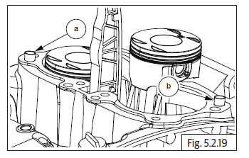
Cylinder Barrel Dowels on Crankcase
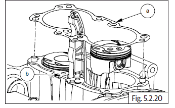
- Install 2 Nos. dowel pins (a) and (b) on upper crankcase.
Cylinder Barrel Gasket on Crankcase
- Ensure the gasket seating area in crankcase is clean.
- Ensure cam chain is routed through a new cylinder base gasket (a) and locate the gasket on crankcase (b).
- Ensure proper seating of the gasket on the dowels on the crankcase.
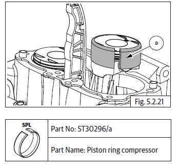
Piston LH in Cylinder Barrel
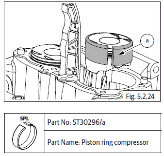
- Ensure piston LH is at its top most position by rotating crankshaft clockwise. Locate piston ring compressor on piston LH.
- Compress piston rings with special tool (a).
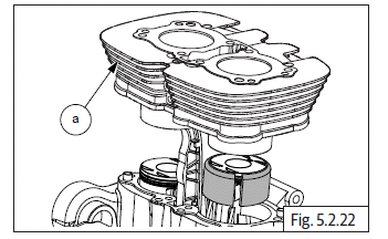
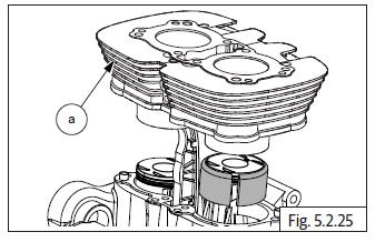
- Position and hold cylinder barrel above crankcase, route cam chain through cylinder barrel bottom and ensure it is supported firmly and suitably at the top.
- Ensure cylinder barrel LH is well lubricated, LH piston is held firmly and straight.
- Gently lower cylinder barrel (a) over the piston ring compressor tool on piston LH, till the piston is halfway into the cylinder barrel.
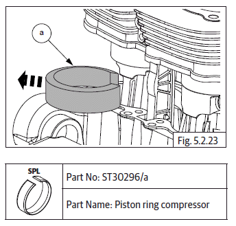
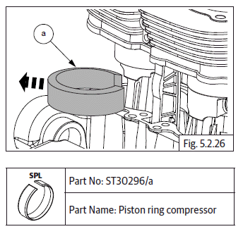
- Hold cylinder barrel firmly in suspended position and remove the piston ring compressor special tool (a) from piston LH.
Piston RH in Cylinder Barrel
- Ensure cylinder barrel RH is well lubricated, RH piston is at its top most position, held firmly and straight.
- Locate piston ring compressor tool (a) over piston RH.
- Gently lower cylinder barrel (a) till piston RH is halfway into the cylinder barrel.
- Hold cylinder barrel firmly in suspended position and remove the piston ring compressor special tool (a) from piston RH.
- Gently lower cylinder barrel further, till it is firmly seated on the crankcase.
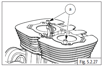
- Locate 2 Nos. dowel pins (a) on cylinder barrel and ensure they are seated properly.
Cylinder Head Gasket on Cylinder Barrel
- Ensure the gasket seating surface on cylinder barrel is clean.
- Ensure cam chain is routed through a new cylinder head gasket.
- Locate head gasket (a) on cylinder barrel and ensure it is properly seated on the dowel pins and cylinder barrel.
See also:
 Royal Enfield Interceptor 650 - Service manual > Oil Bypass
Ensure O-rings (a) are located properly. Install oil bypass pipe (b) into lower crankcase oil gallery. Tighten 2 Nos. Hex socket head screw (M6) (a) to specified torque.
Royal Enfield Interceptor 650 - Service manual > Floating Chain Pad
Hold timing chain (a) suitably and insert chain pad (b) into cylinder barrel with the rubber track facing inside.
 Rider's Manual BMW R 1250 GS GSA
 Owner's Manual Harley-Davidson Sportster XL1200X Forty-Eight
 Owner's Manual Honda CBR650R
 Service manual Honda CBR650
 Owner's Manual Honda PCX125
 Owner's Manual Kawasaki Z1000SX
 Service manual Kawasaki Z1000SX
 Owner's Manual Lexmoto Echo
 Owner's Manual Royal Enfield Interceptor 650
 Service manual Royal Enfield Interceptor 650
 Owner's Manual Yamaha MT-07