 Royal Enfield Interceptor 650 - Service manual > Magneto Cover Sub Assembly
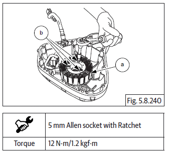
Stator coil with CPS in Magneto cover
- Position stator coil (a) inside magneto cover such that.
- The Crank position sensor is seated at its mounting location.
- Magneto wires and grommet are aligned to the slot on the top of the cover.
- The stator mounting holes are aligned to the mounting holes in magneto cover.
- Locate 3 Nos. Hex socket head bolts (M6) (b) in the stator coil mounting holes and tighten evenly to specified torque.
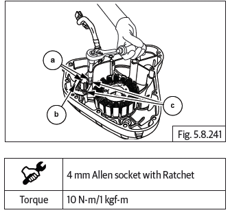
- Locate guide plate (b) over the CPS (a), ensure the mounting holes of the guide plate, CPS are aligned to the mounting holes in magneto cover.
- Locate 2 Nos. Hex socket head screws (M5) (c) on the guide plate and tighten evenly to specified torque.
- Locate dowel pins (a) and (b) into crankcase.
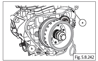
- Install gasket (a), if necessary smear engine oil and ensure it is properly seated on dowels. Do not use any sealant or adhesive.
- Align the magneto cover such that the stator coils are located into the magneto rotor and ensure proper seating of the cover against the gasket.
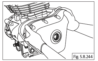
CAUTION Magnetic force from the rotor may cause misalignment of the cover during assembly. please ensure cover is centralized and seating properly before tightening the screws.
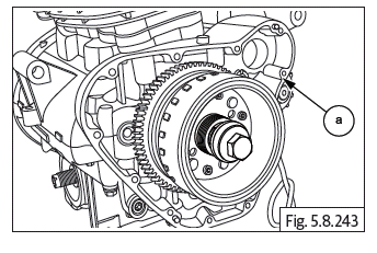
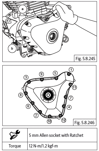
- Locate 12 Nos. Hex socket bolts (M6) (a) on magneto cover (b) and tighten it in a crisscross pattern.
- Tighten the bolts evenly to specified torque.
- Locate O-ring (a) on plug (b).
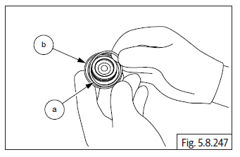
- Assemble plug (M34) (a) on center of magneto cover and tighten it to specified torque.
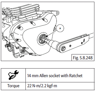
- Ensure the magneto and gear position sensor wiring is correctly routed through the crankcase assembly.
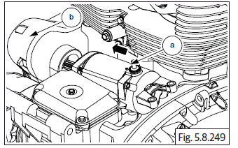
Starter Motor
NOTE
- Do not tap on the starter motor. It may damage the internal parts.
- Inspect the starter driveshaft teeth for any wear- out or damages.
- Locate starter motor (a) into the upper crankcase housing (b) LH.
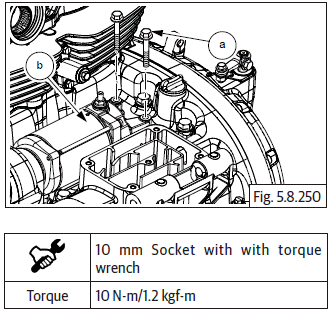
- Locate and install 2 Nos. Hex head flange bolts (M6) (a) on starter motor (b).
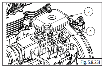
Breather Box
- Locate gasket (a) on breather box cover (b) and assemble breather box cover on engine.
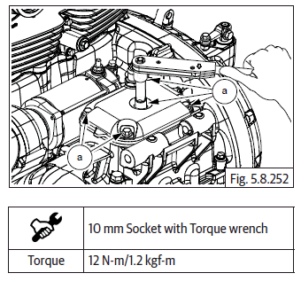
- Install and tighten 5 Nos. Hex-head flange bolts (M6) (a) to specified torque.
- Fit breather hose (a) into intake manifold and install clamp.
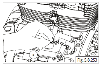
Oil Filter
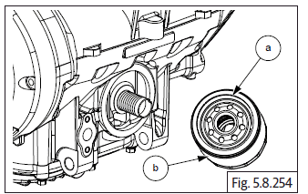
- Ensure O-ring (a) is seated properly over the oil filter (b).
- Apply thin layer of fresh engine oil over O-ring.
- Locate oil filter into crankcase.
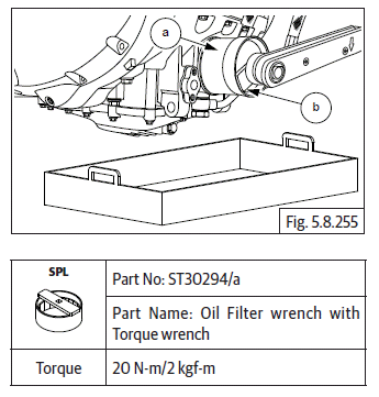
- Tighten oil filter (a) using special tool (b) to specified torque.
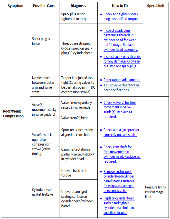
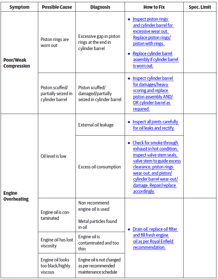
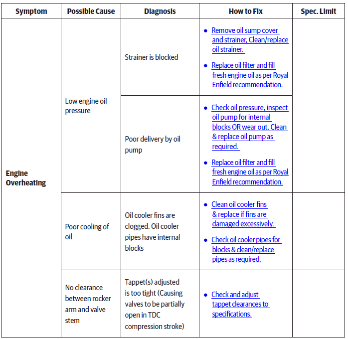
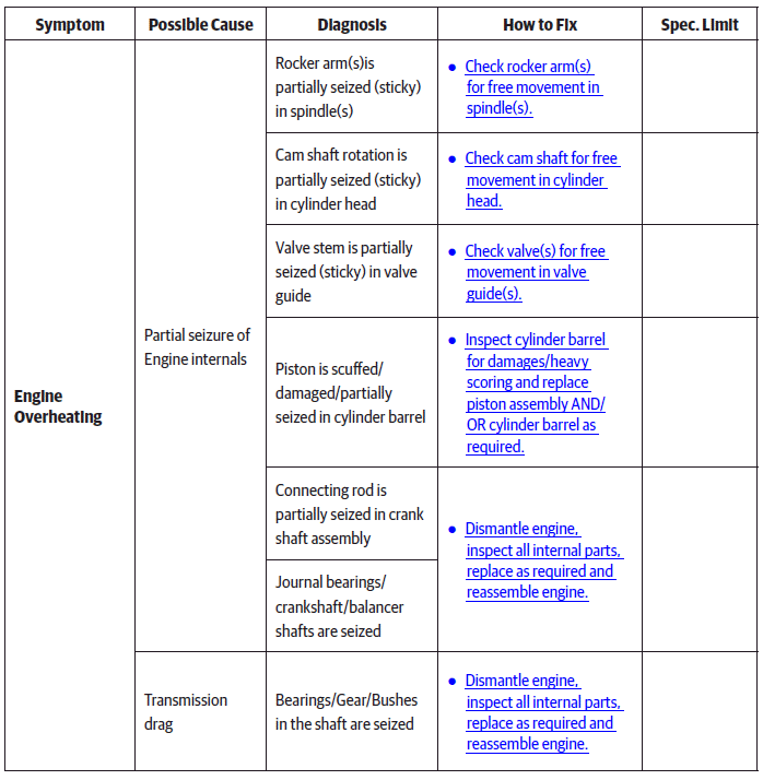
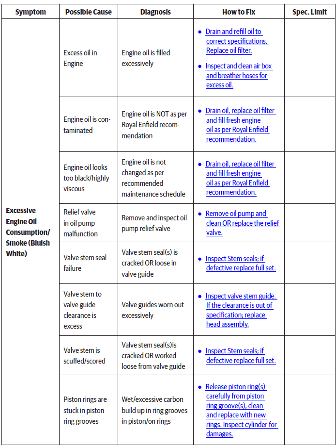
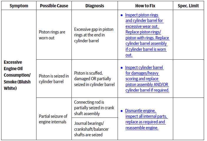
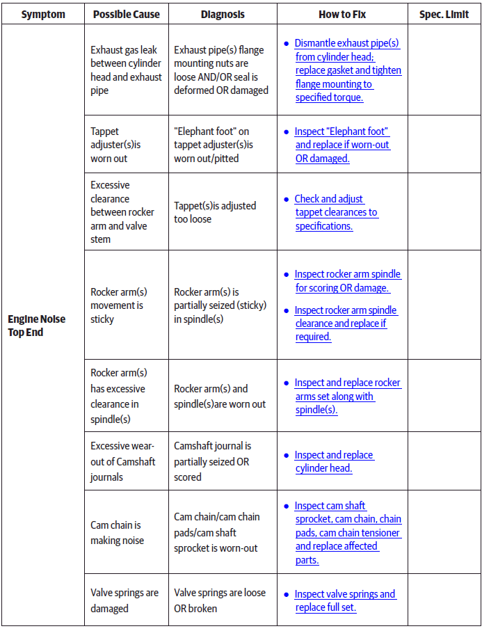
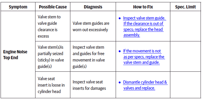
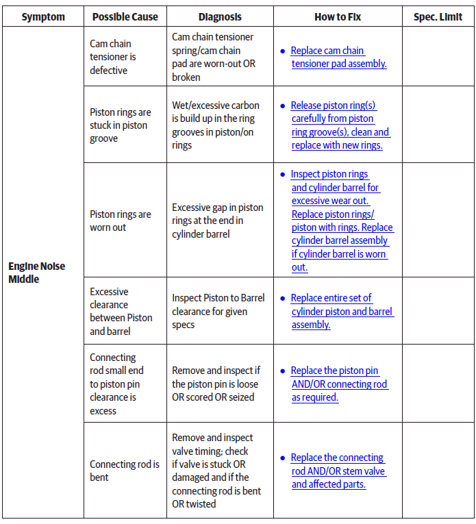
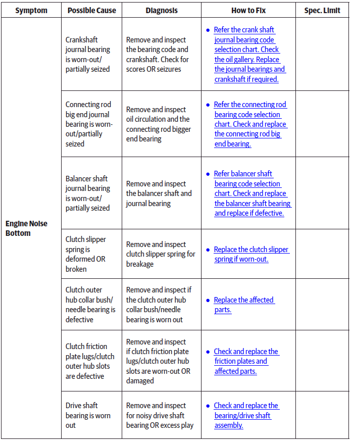
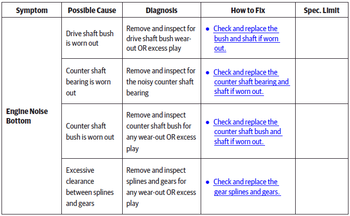
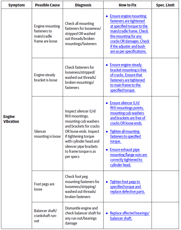
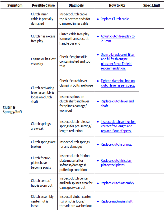
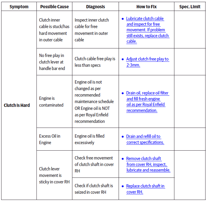
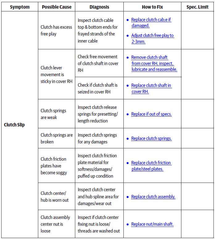
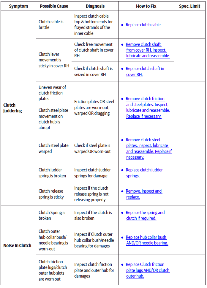
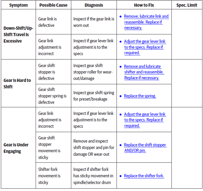
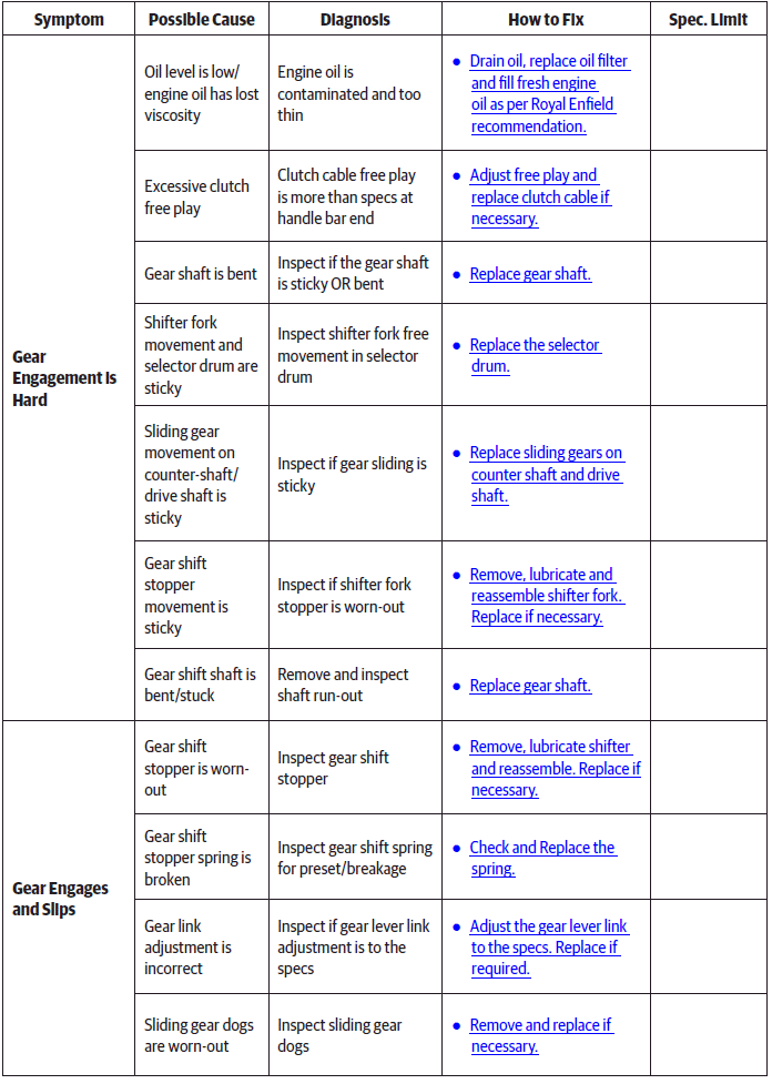
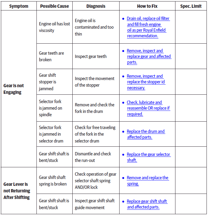
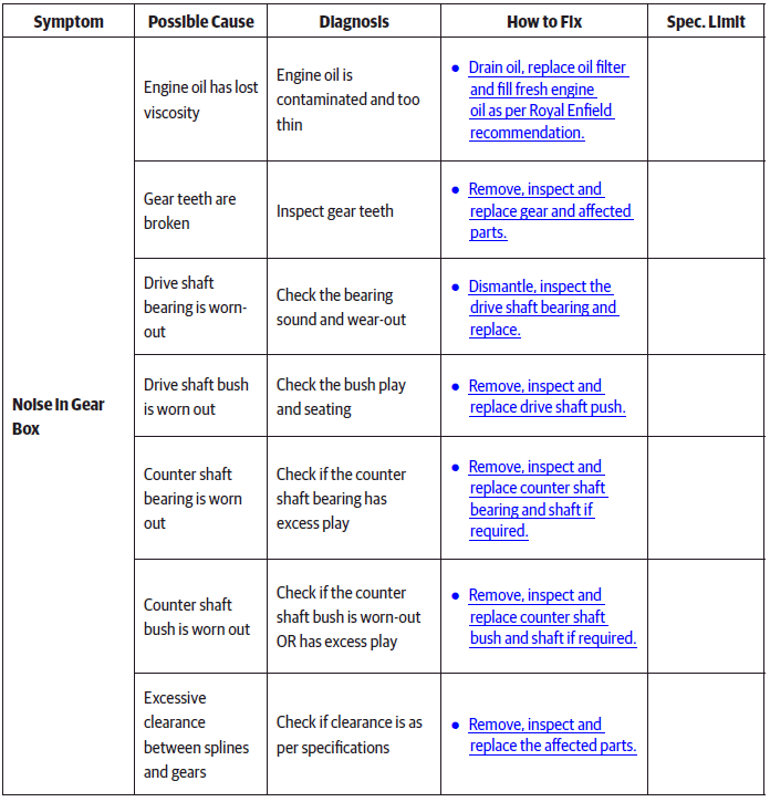
Engine Troubleshooting
See also:
 Royal Enfield Interceptor 650 - Service manual > Tappet Clearance Adjustment
Tappet Clearance Cylinder head LH Ensure "L" mark on camshaft (a) is aligned to cylinder head. Ensure the flat edge of the special tool (a) is correctly located in the slot on the camshaft on RH side and the tool is resting correctly on the cylinder head. Gently rotate crankshaft to ensure proper seating of the tool in the camshaft slot and cylinder head. Loosen tappet adjuster screw locknut (a) with special tool and ensure locknut is sufficiently loose. Insert a screw driver into the tappet adjusting tool (b) and ensure it is seated correctly on the adjuster screw (a). Locate feeler strip (a) between adjuster screw and valve stem as per thickness mentioned below. Gently pull out feeler strip (a) and check if it comes out freely OR with resistance. In case feeler strip comes out freely the adjuster screw has to be tightened. In case feeler strip movement is hard, the adjuster screw must be loosened. Tighten/loosen adjuster screw using screw driver, while simultaneously checking correct and smooth movement of feeler strip. Ensure special tool (a) does not rotate while adjusting the screw. After setting correct gap, remove feeler strip, hold screw driver firmly such that the setting DOES NOT gets distrubed and gently lock the lock nut against rocker arm using special tool (a).
 Rider's Manual BMW R 1250 GS GSA
 Owner's Manual Harley-Davidson Sportster XL1200X Forty-Eight
 Owner's Manual Honda CBR650R
 Service manual Honda CBR650
 Owner's Manual Honda PCX125
 Owner's Manual Kawasaki Z1000SX
 Service manual Kawasaki Z1000SX
 Owner's Manual Lexmoto Echo
 Owner's Manual Royal Enfield Interceptor 650
 Service manual Royal Enfield Interceptor 650
 Owner's Manual Yamaha MT-07