 Royal Enfield Interceptor 650 - Service manual > Tappet Clearance Adjustment
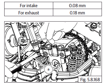
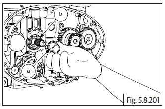
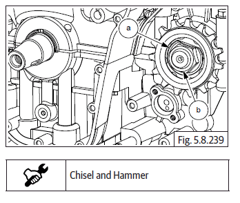
Tappet Clearance Cylinder head LH
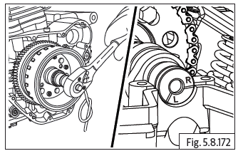
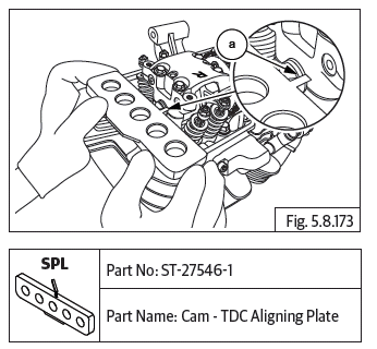
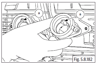
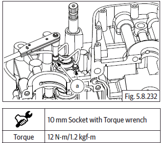
- Ensure "L" mark on camshaft (a) is aligned to cylinder head.
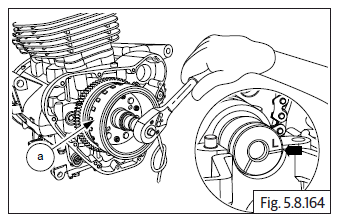
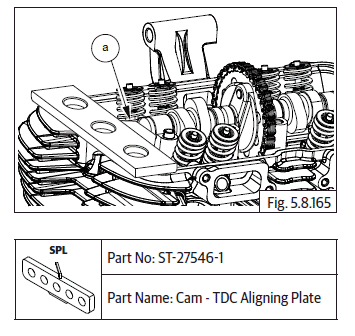
- Ensure the flat edge of the special tool (a) is correctly located in the slot on the camshaft on RH side and the tool is resting correctly on the cylinder head.
- Gently rotate crankshaft to ensure proper seating of the tool in the camshaft slot and cylinder head.
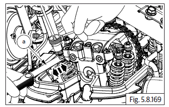
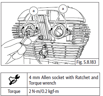
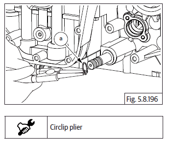
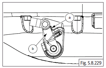
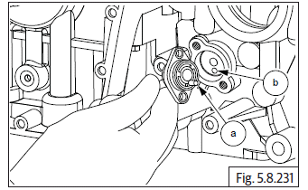
- Loosen tappet adjuster screw locknut (a) with special tool and ensure locknut is sufficiently loose.
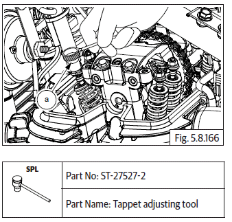
- Insert a screw driver into the tappet adjusting tool (b) and ensure it is seated correctly on the adjuster screw (a).
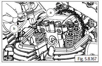
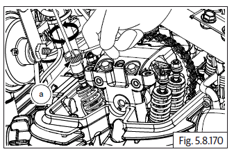
- Locate feeler strip (a) between adjuster screw and valve stem as per thickness mentioned below.
- Gently pull out feeler strip (a) and check if it comes out freely OR with resistance.
- In case feeler strip comes out freely the adjuster screw has to be tightened.
- In case feeler strip movement is hard, the adjuster screw must be loosened.
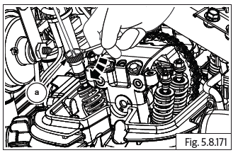
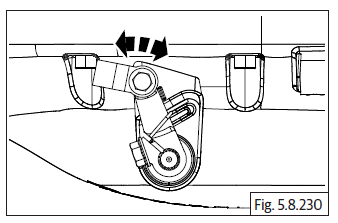
- Tighten/loosen adjuster screw using screw driver, while simultaneously checking correct and smooth movement of feeler strip.
- Ensure special tool (a) does not rotate while adjusting the screw.
- After setting correct gap, remove feeler strip, hold screw driver firmly such that the setting DOES NOT gets distrubed and gently lock the lock nut against rocker arm using special tool (a).
NOTE
- Reconfirm correctness of tappet clearances before final locking of lock nut.
CAUTION Do not adjust tappets with less OR no clearance as it will result in poor compression, valve burn-out and wear-out of tappet adjuster foot.
Do not adjust tappet with high clearance as will result in noise and insufficient opening
- Remove screw driver and both special tools after adjustment is complete.
Tappet Clearance Cylinder Head RH
NOTE
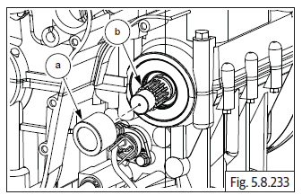
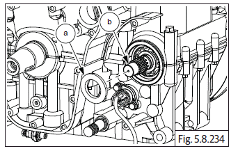
- Ensure "R" mark on camshaft is aligned to cylinder head.
- Ensure the angular edge of the special tool (a) is correctly located in the slot on the camshaft on RH side and the tool is resting correctly on the cylinder head.
- Adjust the RH tappets clearances as mentioned in tappets adjustment LH.
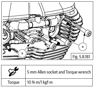
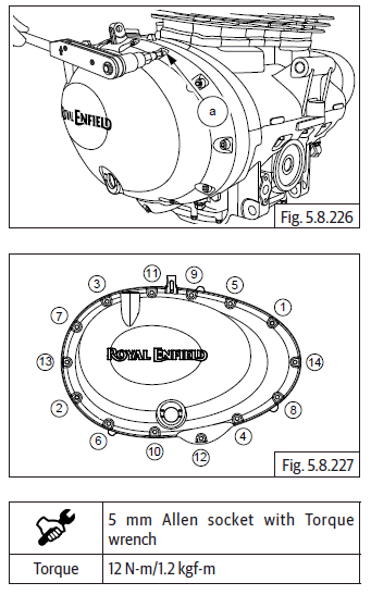
Cover Cylinder Head
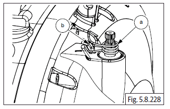
NOTE
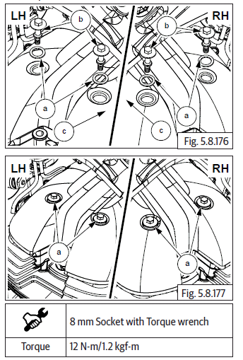
- Ensure the cover-cylinder head seating surface and gasket seating groove are clean.
- Locate new rubber gasket in the groove in cylinder head and ensure it is properly and evenly seated.
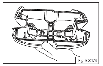
- Locate cylinder head cover (a) on cylinder head with its narrow deep slot facing towards front of the engine.
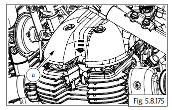
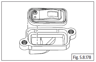
- Assemble new seals washers (a) on the 4 Nos. Hex flange head bolts (M5) (b).
- Locate the bolts on cylinder head cover (c) and tighten bolts to cylinder head evenly to specified torque.
Reed Valves
NOTE
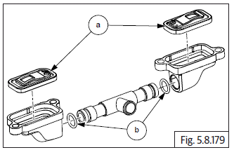
- The reed valve has a rounded edge in one of the corners this should be aligned to the rounded edge in the housing during assembly.
- Loacte reed valves LH & RH (a) in the housings duly ensuring it is seated properly and correctly.
- Assemble new "O" rings (b) on either ends of the connection tube and locate the reed valves housings LH & RH on the connection tube duly ensuring the connection tube is fully inserted into the housings.
- Locate reed valves on cylinder head front side with the hose (a) pointing upwards and ensure the mounting holes are aligned.
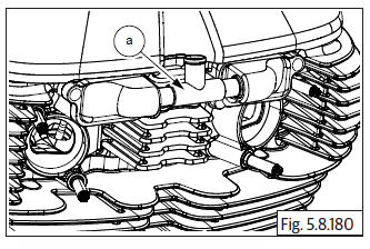
- Locate 2 Nos. each Hex socket head bolts (M6) (a) on the LH and RH reed valves and tighten evenly to specified torque.
Inlet Manifold Rubber Flanges LH & RH
Locate 2 Nos. inlet manifold rubber flanges (a) on the cylinder heads, duly ensuring the "cut away" in the manifolds are matching with the "cut away" in the cylinder head.
- Locate and tighten 2 Nos. each countersunk head bolts (M5) (a) on the manifold rubber flanges on inlet manifold LH & RH.
Star Index
- Locate and tighten 2 Nos. Hex head bolts (M6) (a) on selector fork shaft stopper plate.

- Locate and tighten Hex socket head stepped bolt (M6) (a) on gear shift cam drum.
Star Index Stopper
- Locate spring and stopper plate support (a) on RH lower crankcase and assemble Hex head flange bolt (M6) (b).
NOTE
- Handle stopper plate tension spring carefully else it may damage supporting components.
Shifter Selector Shaft Assembly
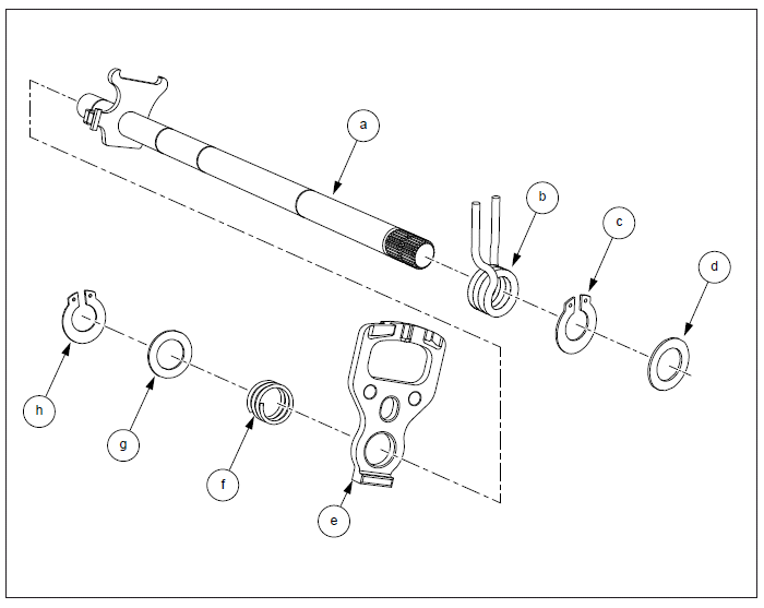
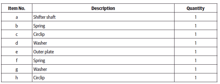
Shifter Selector Shaft
- Assemble inner spring (a) from the longer side of shifter shaft (b).
- Ensure the legs of the spring are correctly located in the plate on the shifter shaft.
- Assemble inner circlip (a) on longer end of shifter shaft (b). Ensure it is properly seated on shifter shaft groove near the spring.
- Assemble 1 st inner washer (a) from the longer end of shifter shaft (b).
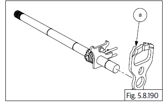
- Assemble outer plate (a) from smaller end of shifter shaft with its projection facing towards the longer end of the shaft.
- Ensure the peg on the shifter shaft is located correctly in the hole on the outer plate (a).
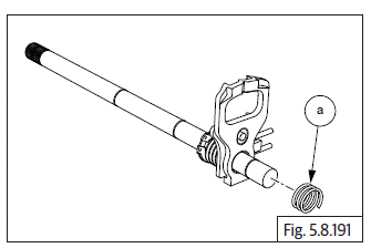
- Assemble outer spring (a) from smaller end of shifter shaft.
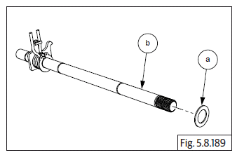
- Assemble outer washer (a) from the smaller end of shifter shaft.
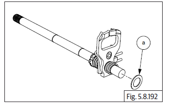
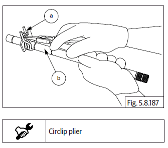
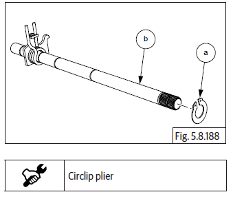
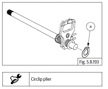
- Assemble outer circlip (a) from smaller end of shifter shaft.
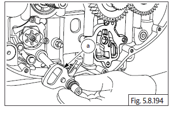
- Insert longer end of the shifter shaft (a) into the hole in the lower crankcase from the RH side.
- Ensure the shifter plate is correctly seated over the star index.
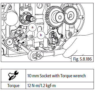
- Assemble washer (a) on the shifter shaft on the LH side.
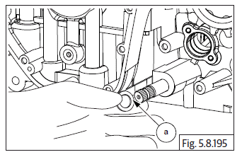
- Assemble circlip (a) on the shifter shaft at the LH side and ensure it is correctly seated and locked in the groove on the shifter shaft.
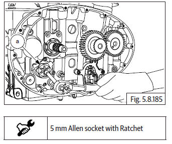
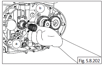
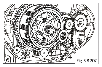
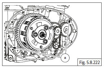
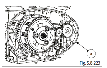
Oil Pump
- Locate oil pump mounting point below crankshaft gear in RH crankcase.
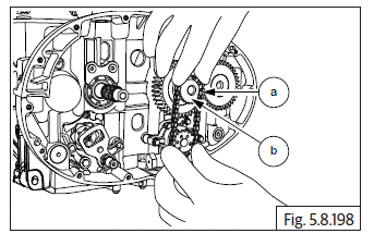
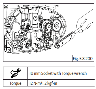
- Assemble 4 Nos. Hex flange head bolts (M6) (a) on oil pump (b) and tighten bolts to specified torque.
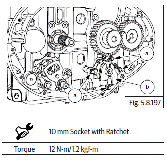
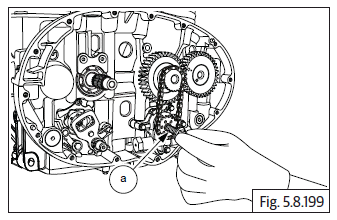
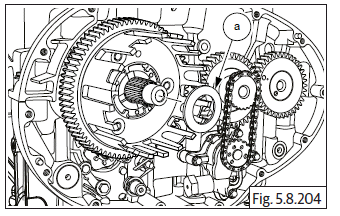
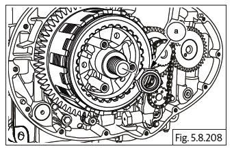
- Locate and fit oil pump drive chain (a) on crankshaft gear (b) and sprocket on oil pump.
- Locate Hex flange head bolt (M6) (a) on oil pump and tighten to specified torque.
NOTE
- Lock the crank shaft by using special tool to prevent rotation while tightening bolt.
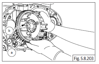
Clutch Plate Assembly
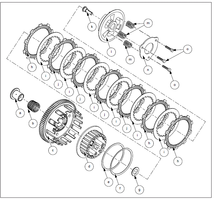
Clutch Assembly
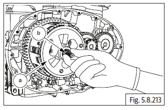
- Ensure collar on bush (a) is facing inward and assemble it on countershaft (b). Ensure it is seated properly.
- Assemble needle bearing (a) on countershaft (b).
- Locate clutch housing (a) on counter shaft, with its lugs (b) facing outside.
- Ensure the clutch housing gear is correctly meshed with the gear on crankshaft.
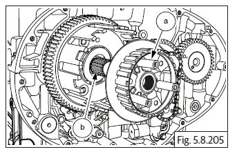
- Assemble thrust washer (a) on countershaft.
- Locate bell assembly (a) on the splines on counter shaft (b).
- Locate the anti-judder steel washer-plain, in the groove in the clutch bell.
- Assemble Belleville washer over judder washer in the clutch bell.
- Ensure the "hump" of the belleville washer is facing inside and seated against the judder washer.
- Assemble 1 st friction plate with larger ID (less friction area) ensuring the splines of the plate are correctly positioned and located on the clutch housing.
- Assemble 1 st steel plate ensuring the splines on the plate are correctly positioned and located on the clutch bell.
- Assemble 2 nd friction plate on the clutch housing and ensure it is seated against the 1 st steel plate.
- Assemble 2 nd steel plate on clutch bell.
- Assemble 3 rd friction plate on clutch housing.
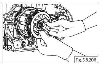
- Assemble washer (a) on countershaft.
- Locate the Hex "U" nut (M17) (a).
CAUTION Hex U nut is left hand thread. Turn anticlockwise to tighten nut on shaft.
- Locate and hold special tool on clutch assembly and tighten clutch hub nut to specified torque.
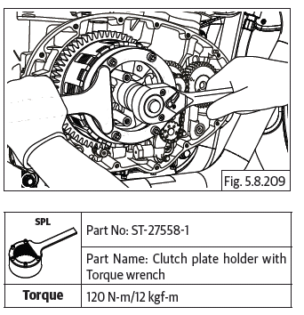
- Remove special tool and further assemble the following
- 3 rd Steel plate on clutch bell.
- 4 th Friction plate on clutch housing.
- 4 th Steel plate on clutch bell.
- 5 th Friction plate on clutch housing.
- 5 th Steel plate on clutch bell.
- Locate 6 th friction plate (a) with larger ID (less friction area) on clutch hub (b) and ensure it is seated properly against the inner face of the clutch hub.
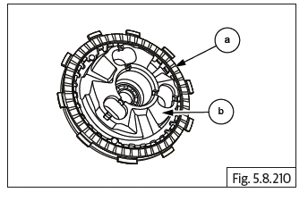
- Locate 6 th steel plate (a) on the splines in clutch hub (b) and ensure it is properly seated against the 6 th friction plate.
- Locate 7 th friction plate (a) with larger ID (less friction area) on clutch hub (b) such that its lugs are offset and between 2 lugs of the 6 th friction plate.
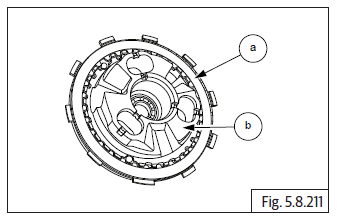
- Locate clutch hub (a) into clutch bell duly ensuring the following:
- Insert pull rod (b) into clutch housing from the inside, such that the serrations on the pull rod are facing outside.
- Ensure pull rod is fully and properly seated against the bearing on the inside.
- The outer lugs of 7 th friction plate are correctly located in the INNER slots of the clutch housing.
- The outer lugs of 6 th friction plate are correctly located in the OUTER slots of the clutch housing.
- The 3 lugs of the clutch hub are correctly positioned between the 3 slots in the clutch bell. (Gently rotate clutch hub back and forth, to match the slots of the clutch bell).
- The three mounting studs of the clutch bell are central to the slots in the clutch hub.
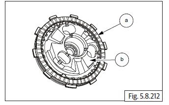
- Insert 3 Nos. compression springs (a) in hub.
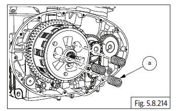
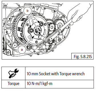
- Locate pressure plate (a) on clutch hub with the words "OUT" and "FR" facing outside.
- Assemble 3 Nos. Hex bolts (M6) (b) and tighten pressure to clutch hub, sequentially to specified torque.
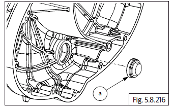
Oil Level Window in Clutch Cover
- Locate new oil window (a) on clutch cover with the window facing towards clutch cover outer and gently press till it is seated fully inside.
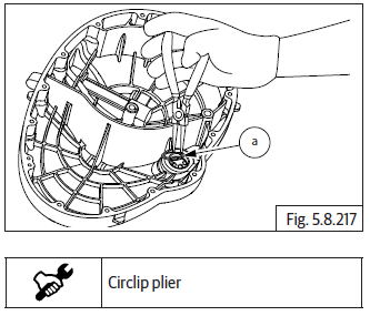
- Assemble circlip (a) in the groove in clutch cover to lock the oil level window in place.
- Ensure circlip is correctly locked in the clutch cover.
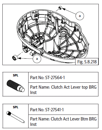
Clutch Actuating Lever Assembly
- Ensure needle bearings (a) are assembled in the clutch cover.
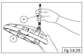
- Insert clutch actuating shaft (a) into clutch cover (b) with the gear facing inside and the splines facing outside.
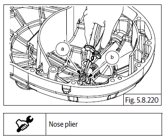
- Assemble washer (b) on the shaft bottom inside the clutch cover.
- Assemble E-clip (a) in the slot in shaft bottom inside clutch cover.
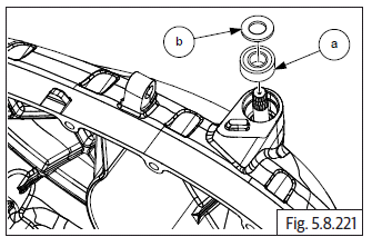
- Assemble new oil seal (a) into clutch cover at the top with the lips facing down.
- Assemble washer (b) above oil seal.
Clutch Cover
- Ensure the 2 Nos. dowel pins (a) are seated properly on crankcase.
- Install gasket (a) on crankcase if necessary smear engine oil and ensure it is properly seated on dowels. Do not use any sealant or adhesive.
- Ensure racks on the clutch pull rod is facing towards the rear of the engine.
- Hold the clutch cover (a) in position, rotate the clutch actuating shaft to ensure it is engaged correctly with the pull rod and gently tap cover inside to seat it on the dowels and crankcase.
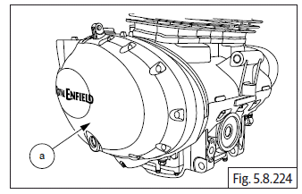
- Locate 14 Nos. Hex socket bolts (M6) (a) on clutch cover and tighten them crisscross pattern.
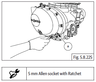
- Tighten bolts (a) evenly to specified torque.
- Assemble clutch release spring (a) on shaft with the "L" bend positioned against the lug (b) in clutch cover.
- Rotate clutch shaft (b) clockwise till it stops. Ensure pinch bolt is sufficiently loose, position clutch lever on shaft at 11 'O' clock position and the inner side of the arm is aligned to the reference mark (a) on the clutch cover.
- Tighten pinch bolt sufficiently such that the arm is firmly clamped on the shaft.
- Position the upper leg of the spring against the inside of the clutch release arm and check for proper spring action.
Gear Position Sensor (GPS)
- Assemble gear position sensor on the LH side of lower crankcase duly ensuring the lug (a) in the GPS is located into the hole (b) in gear selector drum.
- Position cable holder (a) over the GPS.
- Assemble 2 Nos. Hex flange head bolts (M6) (a) on the cable holder and tighten cable holder and GPS to the crankcase on the LH side to specified torque.
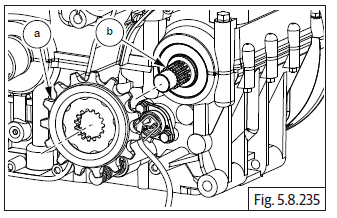
FD Sprocket
- Assemble spacer (a) on drive shaft (b) on the LH side.
- Locate oil seal (a) with its open end facing inwards on the crankcase on LH side and tap it in gently till the outer surface of the oil seal is flush with the crankcase (b)
- Assemble FD sprocket (a) on countershaft (b).
- Install splined washer (a) on driveshaft (b).
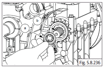
- Assemble FD sprocket nut (M20) (a) on driveshaft.
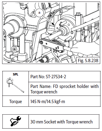
- Locate special tool (a) over FD sprocket and tighten nut to specified torque.
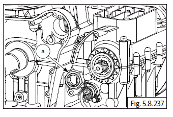
- Gently bend the tab washer (a) outer, to seat against a flat surface of the hex nut (b) with a flat chisel to prevent the nut from loosening during use.
See also:
 Royal Enfield Interceptor 650 - Service manual > Rocker Arms in Carriers LH and RH
Exhaust rocker arm in carrier "L" Place the carrier (a) on a work table with the mark "L" facing upwards. Gently depress the spring (a) and install into rocker carrierrs (b). Locate rocker arm (b) with the marking "EL" into carrier "L" duly ensuring the following. The roller of the rocker arm is inserted from the side marked "L". The tappet adjustment screws are facing upwards. Ensure the holes are aligned and insert spindle with its small chamfer side in the carrier. Ensure cut away in spindle is correctly aligned to the carrier mounting hole. Align and insert the spindle (c) into rocker carrier and rocker arm.
Royal Enfield Interceptor 650 - Service manual > Magneto Cover Sub Assembly
Stator coil with CPS in Magneto cover Position stator coil (a) inside magneto cover such that. The Crank position sensor is seated at its mounting location. Magneto wires and grommet are aligned to the slot on the top of the cover. The stator mounting holes are aligned to the mounting holes in magneto cover. Locate 3 Nos. Hex socket head bolts (M6) (b) in the stator coil mounting holes and tighten evenly to specified torque. Locate guide plate (b) over the CPS (a), ensure the mounting holes of the guide plate, CPS are aligned to the mounting holes in magneto cover. Locate 2 Nos. Hex socket head screws (M5) (c) on the guide plate and tighten evenly to specified torque. Locate dowel pins (a) and (b) into crankcase. Install gasket (a), if necessary smear engine oil and ensure it is properly seated on dowels. Do not use any sealant or adhesive. Align the magneto cover such that the stator coils are located into the magneto rotor and ensure proper seating of the cover against the gasket.
 Rider's Manual BMW R 1250 GS GSA
 Owner's Manual Harley-Davidson Sportster XL1200X Forty-Eight
 Owner's Manual Honda CBR650R
 Service manual Honda CBR650
 Owner's Manual Honda PCX125
 Owner's Manual Kawasaki Z1000SX
 Service manual Kawasaki Z1000SX
 Owner's Manual Lexmoto Echo
 Owner's Manual Royal Enfield Interceptor 650
 Service manual Royal Enfield Interceptor 650
 Owner's Manual Yamaha MT-07