 Royal Enfield Interceptor 650 - Service manual > Oil Level Window
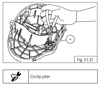
- Remove the circlip (a) on the oil level window inside clutch cover.
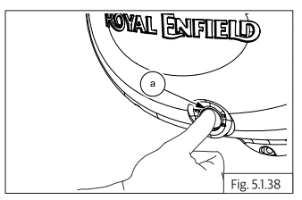
- Gently press oil window (a) from outer side to remove from clutch cover.
Clutch Plates
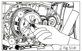
CAUTION Bolts are under spring tension. Loosen bolts progressively and slowly until spring tension is completely released.
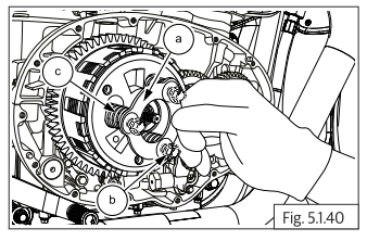
- Loosen 3 Nos. Hex flange head bolts (M6) (a) on the pressure plate evenly and slowly until tension is released completely.
- Hold pressure plate (a) and remove the bolts (b).
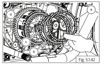
- Remove pressure plate and spring (c) from clutch hub.
- Remove clutch hub (b) along with 2 friction plates, 1 steel plate and pull rod (a) from the clutch bell.
- Remove the pull rod from the inner side of clutch bell.
- Remove 1 st friction plate (a), steel plate (b) and 2 nd friction plate (c) from clutch hub (d).
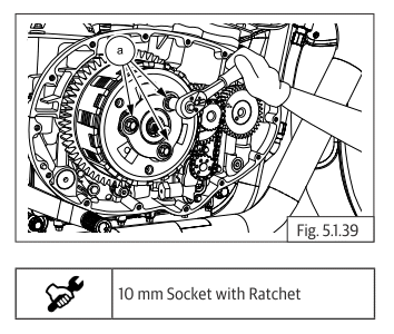
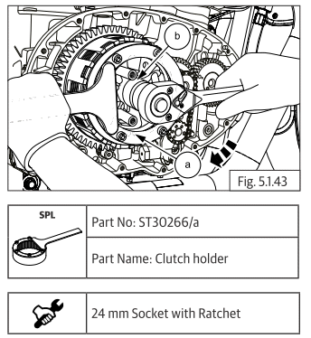
- Locate special tool (a) on clutch center (b) and ensure it is seated fully on the splines.
- Hold the clutch center firmly and remove Hex "U" nut (M17) (b) by rotating clockwise.
CAUTION Hex "U" nut is a left hand thread. Wrong rotation may damage the threads.
- Remove Hex U nut and washer from countershaft.
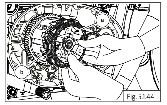
- Remove special tool and pull out clutch bell assembly (a) from the counter shaft along with the remaining 6 plates (b) (3 each friction and steel plates) from the clutch housing.
NOTE
- If the plates are to be reused, suitably mark the plates so that they can be reassembled in the same sequence as it was before dismantling.
- Remove thrust washer (a) from counter shaft.
- Remove clutch housing (a) from counter shaft.
- Remove the needle bearing (a).
- Remove collar bush (a) from counter shaft.
Oil Pump
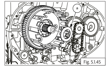
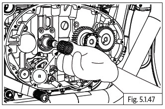
- Loosen and remove Hex flange bolt (M5) (a) on oil pump sprocket.
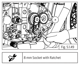
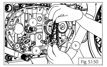
- Gently pull out the sprocket (a) from oil pump shaft.
- Release and remove chain (b) from the teeth on crankshaft sprocket (c).
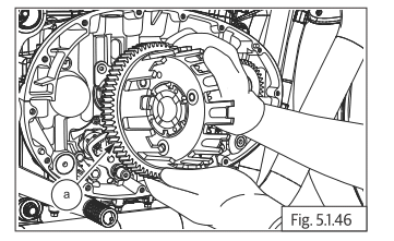
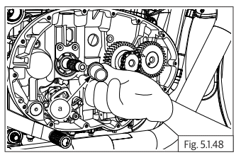
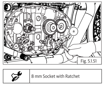
- Loosen and remove 4 Nos. Hex flange head bolts (M5) (a) to separate oil pump from crankcase.
- Remove the oil pump (a) along with O-ring (b).
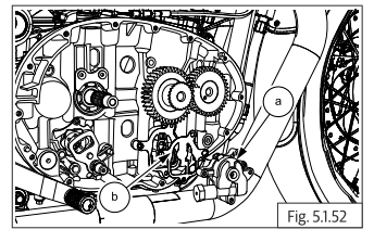
NOTE
- Inspect O-ring for any deformation OR damage and replace if required.
- The oil pump does not have any serviceable parts, hence as to be replaced only as a complete assembly.
See also:
 Royal Enfield Interceptor 650 - Service manual > Clutch Cable on Clutch Cover
Disconnect clutch cable assembly (a) from clutch cover (b). Refer clutch cable dismantling procedure.
Royal Enfield Interceptor 650 - Service manual > Gear Shifter Shaft
Remove the circlip (a) from shifter shaft (b) on engine LH side. Remove the washer (a) from shifter shaft. Gently pull out shifter shaft assembly (a) from engine RH side. Remove circlip (a) from shorter end of shifter shaft (b). Remove washer (a) from shorter end of shifter shaft (b). Remove spring (a) from shifter shaft (b). Remove plate (a) from shorter end of shifter shaft (b). Remove circlip (a) from longer end of shifter shaft (b). Remove washer (a) from longer end of shifter shaft (b). Expand spring lugs and pull out spring (a) from longer end of shifter shaft (b).
 Rider's Manual BMW R 1250 GS GSA
 Owner's Manual Harley-Davidson Sportster XL1200X Forty-Eight
 Owner's Manual Honda CBR650R
 Service manual Honda CBR650
 Owner's Manual Honda PCX125
 Owner's Manual Kawasaki Z1000SX
 Service manual Kawasaki Z1000SX
 Owner's Manual Lexmoto Echo
 Owner's Manual Royal Enfield Interceptor 650
 Service manual Royal Enfield Interceptor 650
 Owner's Manual Yamaha MT-07