 Royal Enfield Interceptor 650 - Service manual > Oil Strainer
- Loosen and remove 2 Nos. Hex flange head bolts (M6) (a) to remove oil strainer (b) along with O-ring (c).
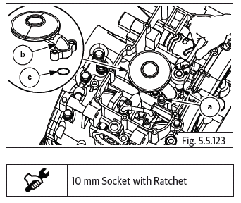
CAUTION Do not reuse O-ring. Always use new O-ring during installation.
Oil Bypass
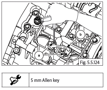
- Loosen and remove pan head screw (M6) (a) to remove bypass (b) from crankcase.
Crankcase Fasteners
Fasteners on Upper Crankcase
- Support crankcase assembly on suitable wedges such that the fasteners on the upper crankcase can be removed.
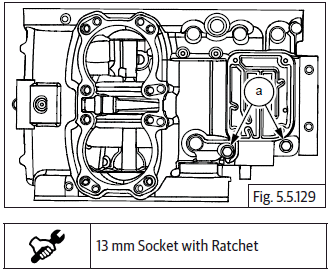
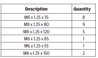
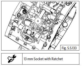
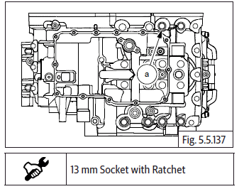
- Loosen and remove 2 Nos. Hex flange bolts M8 X 1.25 X 105 (a) near oil filler hole on RH side (clutch side) of upper crankcase.
- Loosen and remove 1 No. Hex flange bolt M8 X 1.25 X 80 (a) near breather box housing on RH side (clutch side) of upper crankcase.
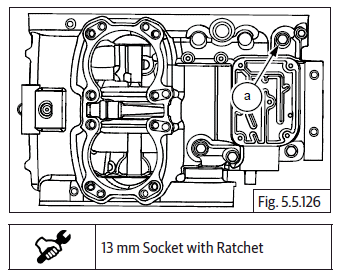
- Loosen and remove 1 No. Hex flange bolt M6 X 1 X 35 (a) from the rear RH side (clutch side) of upper crankcase.
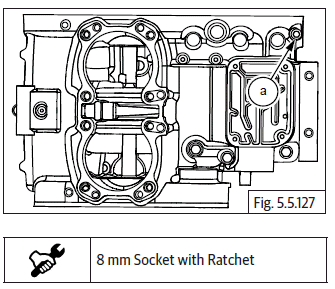
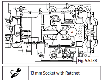
- Loosen and remove 1 No. Hex flange bolt M8 X 1.25 X 45 (a) from starter motor recess on LH side (magneto side) of upper crankcase.
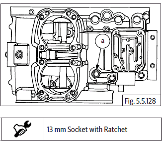
- Loosen and remove 2 Nos. Hex flange bolt M8 X 1.25 X 80 (a) (1 each from starter motor recess and FD sprocket spigot area) on LH side (magneto side) of upper crankcase.
Fasteners on Lower Crankcase
- Gently invert crankcase assembly such that the upper crankcase is resting firmly on suitable wedges and the fasteners from lower crankcase can be removed.
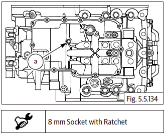
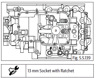
- Loosen and remove 5 Nos. Hex flange bolts M6 X 1 X 35 (a) from the front end of lower crankcase.
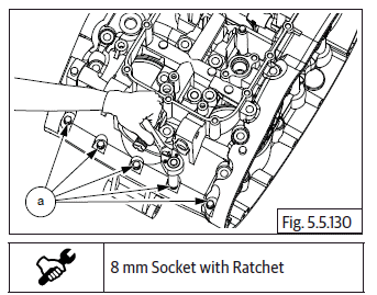
- Loosen and remove 3 Nos. Hex flange bolts M6 X 1 X 35 (a) from the rear end of lower crankcase.
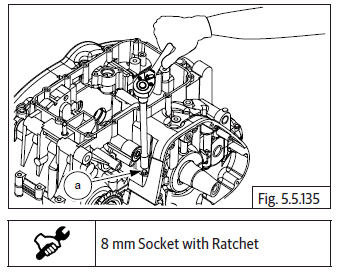
- Loosen and remove 6 Nos. Hex flange bolts M8 X 1.25 X 80 (a) in crisscross pattern from the centre of lower crankcase inside oil sump area.
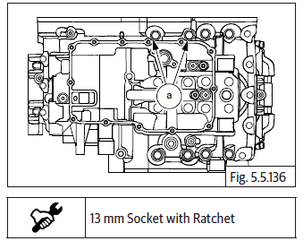
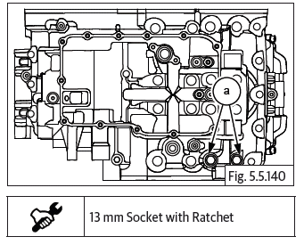
- Loosen and remove 2 Nos. Hex flange bolts M8 X 1.25 X 120 (a) from oil filter element mounting area in the lower crankcase front side.
- Loosen and remove 1 No. Hex flange head bolt M6 X 1 X 85 (a) from the centre of lower crankcase inside oil sump area.
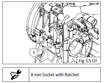
- Loosen and remove 1 No. Hex flange head bolt M6 X 1 X 55 (a) from the lower crankcase LH side (Magneto side).
- Loosen and remove 2 Nos. Hex flange bolts M8 X 1.25 X 150 (a) from the lower crankcase LH side (Magneto side).
- Loosen and remove 1 No. Hex flange bolt M8 X 1.25 X 120 (a) from the lower crankcase LH side (Magneto side).
- Loosen and remove 1 No. Hex flange bolt M8 X 1.25 X 80 (a) from the lower crankcase LH side (Magneto side).
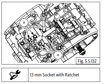
- Loosen and remove 2 Nos. Hex flange bolts M8 X 1.25 X 120 (a) from the lower crankcase RH side (clutch side).
- Loosen and remove 2 Nos. Hex flange bolts M8 X 1.25 X 80 (a) from the lower crankcase RH side (clutch side).
See also:
 Royal Enfield Interceptor 650 - Service manual > Cylinder Head
Remove oil temperature sensor. CAUTION Cylinder bolts are one time usage only. Always use new head bolts during installation. Dispose old head bolts suitably. Loosen and remove 8 Nos. Hex head bolts (M10) (a) in crisscross pattern on cylinder head. Support cam chain suitably and gently remove cylinder head (a) from cylinder barrel (b). Remove the cylinder head gasket (a) from cylinder barrel (b).
Royal Enfield Interceptor 650 - Service manual > Splitting Crankcase
Ensure the upper crankcase is supported firmly on suitable wedges with the lower crankcase facing upwards. Gently separate the lower crankcase from the upper crankcase by slightly tapping on the tabs (a) provided in lower crankcase, to release from the dowels and sealing gasket material. Remove lower crankcase along with the gear selector drum, from the upper crankcase.
 Rider's Manual BMW R 1250 GS GSA
 Owner's Manual Harley-Davidson Sportster XL1200X Forty-Eight
 Owner's Manual Honda CBR650R
 Service manual Honda CBR650
 Owner's Manual Honda PCX125
 Owner's Manual Kawasaki Z1000SX
 Service manual Kawasaki Z1000SX
 Owner's Manual Lexmoto Echo
 Owner's Manual Royal Enfield Interceptor 650
 Service manual Royal Enfield Interceptor 650
 Owner's Manual Yamaha MT-07