 Royal Enfield Interceptor 650 - Service manual > Splitting Crankcase
Engine / Engine Dismantling / Splitting Crankcase
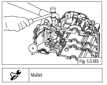
- Ensure the upper crankcase is supported firmly on suitable wedges with the lower crankcase facing upwards.
- Gently separate the lower crankcase from the upper crankcase by slightly tapping on the tabs (a) provided in lower crankcase, to release from the dowels and sealing gasket material.
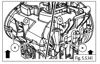
- Remove lower crankcase along with the gear selector drum, from the upper crankcase.
CAUTION Ensure all the mounting fasteners on the lower and upper crankcase have been removed.
Ensure the gear shift forks are not jammed in the grooves in the gears.
Ensure the dowels are removed from the upper and lower crankcases.
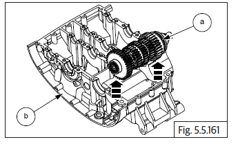
Balancer Shaft
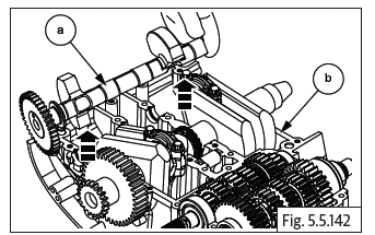
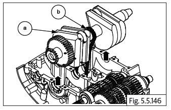
- Gently lift and remove balancer shaft (a) from upper crankcase (b).
Timing Chain Tensioner Pad
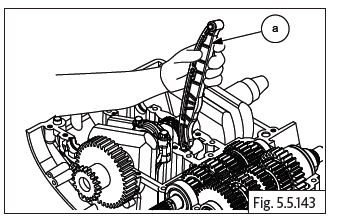
- Gently pull out timing chain tensioner pad (a) from crankcase.
Connecting Rod
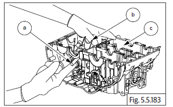
- Loosen and remove 2 Nos. bi-hexagonal bolts (M9) (a) to disconnect connecting rod big end (b) from crankshaft (c).
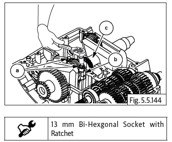
- Split the connecting rod's big end.
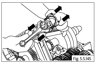
- Repeat same procedure for other connecting rod.
NOTE
- Make sure to mark connecting rod suitably to retain original position during installation.
Crankshaft Assembly
CAUTION Crankcase and connecting rod bolts are one time use only.
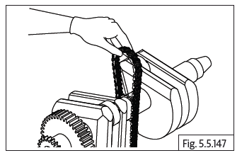
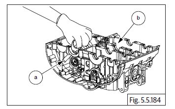
- Gently lift and remove crankshaft assembly (a) from crankcase along with the cam chain (b).
- Release cam chain from the sprocket on the center of the crankshaft and remove.
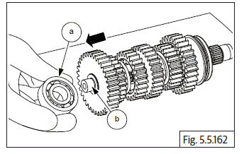
Countershaft
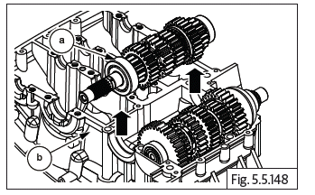
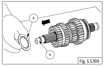
- Gently lift to remove transmission countershaft with gear assembly (a) from upper crankcase (b).
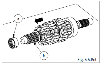
- Remove the bearing (a) from the countershaft smaller end (b).
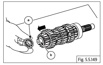
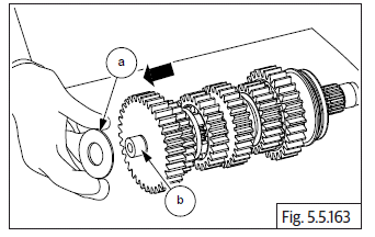
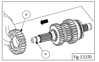
- Remove thrust washer (a) from countershaft (b).
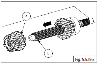
- Remove the 2 nd gear (16 teeth) (a) from the countershaft (b).
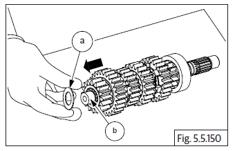
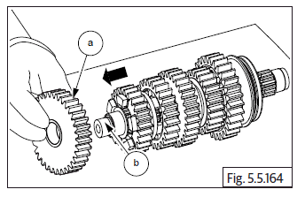
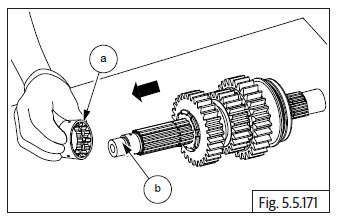
- Remove the 6 th gear (26 teeth) (a) from the countershaft (b).
- Remove plain bush (a) from the countershaft (b).
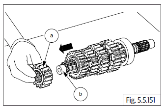
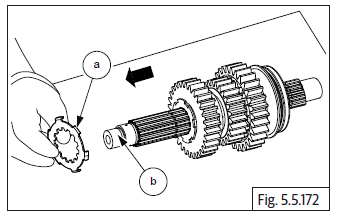
- Remove the splined washer (a) from the countershaft (b).
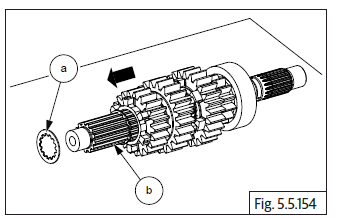
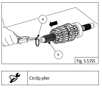
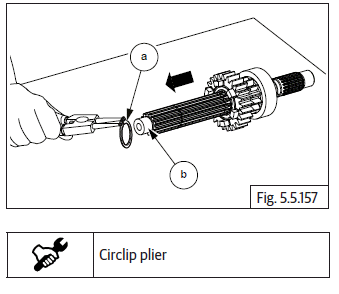
- Remove the outer circlip (a) from the countershaft (b).
- Remove the 3 rd and 4 th double gears (a) from the countershaft (b).
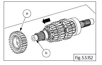
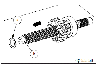
- Remove the inner circlip (a) from the countershaft (b).
- Remove the thrust washer (a) from countershaft (b).
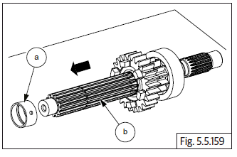
- Remove the plain bush (a) from the countershaft (b).
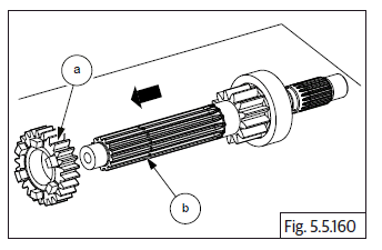
- Remove the 5 th gear (24 teeth) (a) from the countershaft (b).
Driveshaft
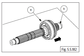
- Gently lift and remove driveshaft with gear assembly (a) from upper crankcase (b).
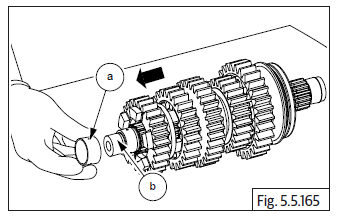
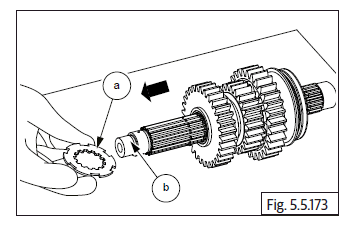
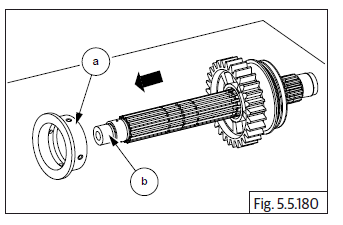
- Remove bearing (a) from non splined end of driveshaft (b).
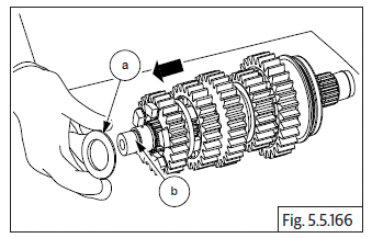
- Remove thrust washer (a) from non splined end of driveshaft (b).
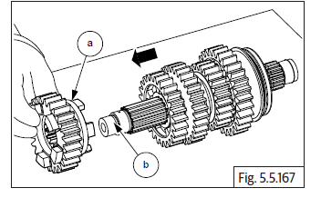
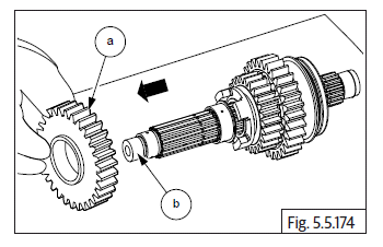
- Remove 1 st gear (a) from non splined end end of driveshaft (b).
- Remove splined bush (a) from driveshaft (b).
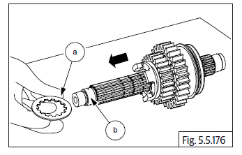
- Remove thrust washer (a) from driveshaft (b).
- Remove 5 th gear (a) from the driveshaft (b).
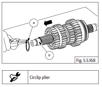
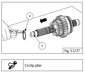
- Remove 4 th circlip (a) from groove in the driveshaft (b).
- Remove splined thrust washer (a) from driveshaft (b).
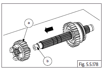
- Remove 4 th gear (a) from driveshaft (b).
- Remove splined bush (a) driveshaft (b).
- Remove the splined lock washer (a) from driveshaft (b).
- Rotate thrust washer (a) such that the inner splines aligned to the splines on the driveshaft and remove from driveshaft (b).
- Remove 3 rd gear (a) from driveshaft (b).
- Remove splined bush (a) from driveshaft (b).
- Remove splined thrust washer (a) driveshaft (b).
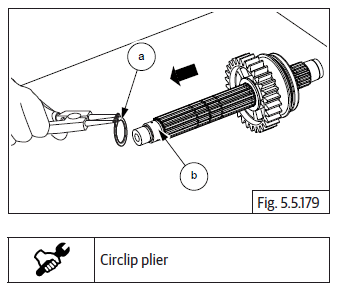
- Remove 2 nd circlip (a) from groove on driveshaft (b).
- Remove 6 th gear (a) from driveshaft (b).
- Remove 1 st circlip (a) from groove on driveshaft (b).
- Remove collar bush (a) from driveshaft (b).
- Remove the 2 nd gear (a) from driveshaft (b).
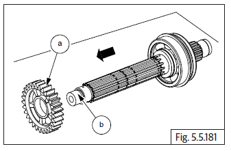
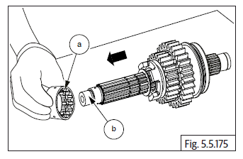
- Gently tap and remove the bearing (a) from the driveshaft (b).
Selector Fork and Spindles
- Support inner selector fork (b) and pullout spindle (a) from the RH side of lower crankcase (c).
- Support the 2 inner selector forks and pull out the spindle (a) from the RH side of lower crankcase (b).
Gear Shift Cam Drum
- Gently drive out gear shift cam drum (a) from the LH side of lower crankcase.
See also:
 Royal Enfield Interceptor 650 - Service manual > Oil Strainer
Loosen and remove 2 Nos. Hex flange head bolts (M6) (a) to remove oil strainer (b) along with O-ring (c).
 Rider's Manual BMW R 1250 GS GSA
 Owner's Manual Harley-Davidson Sportster XL1200X Forty-Eight
 Owner's Manual Honda CBR650R
 Service manual Honda CBR650
 Owner's Manual Honda PCX125
 Owner's Manual Kawasaki Z1000SX
 Service manual Kawasaki Z1000SX
 Owner's Manual Lexmoto Echo
 Owner's Manual Royal Enfield Interceptor 650
 Service manual Royal Enfield Interceptor 650
 Owner's Manual Yamaha MT-07