 Honda CBR650 - Service manual > Service information
GENERAL
- The crankcase must be separated to service the following:
- Transmission
- Crankshaft
- Piston/connecting rod/cylinder
- The following components must be removed before separating the crankcase:
- Engine
- Clutch
- Gearshift linkage
- Starter clutch
- Flywheel
- Cylinder head
- Oil pan
- Oil pump
- Oil cooler
- Starter motor
- Water pump
- EOP switch
- VS sensor
- Neutral switch
- Be careful not to damage the crankcase mating surfaces when servicing.
- Prior to assembling the crankcase halves, apply sealant to their mating surfaces. Wipe off excess sealant thoroughly.
Troubleshooting
Hard to shift
- Improper clutch operation
- Improper engine oil viscosity
- Bent shift fork
- Bent shift fork shaft
- Bent shift fork claw
- Damaged shift drum guide groove
- Bent gearshift spindle
Transmission jumps out of gear
- Worn gear dogs
- Worn gear shifter groove
- Bent shift fork shaft
- Broken shift drum stopper arm
- Broken shift drum stopper arm return spring
- Worn or bent shift forks
- Broken gearshift spindle return spring
Excessive engine noise
- Worn or damaged transmission gear
- Worn or damaged transmission bearings
Component location
Crankcase
SEPARATION
Refer to Service Information for removal of necessary parts before separating the crankcase.
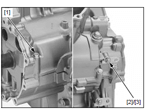
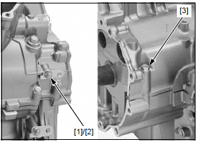
Remove the crankcase 6 x 50 mm bolt [1] on the upper side of the crankcase.
Remove the bolt [2] and wire stay [3] on the lower side of the crankcase.
Place the engine upside down.
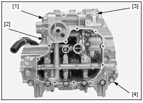
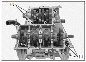
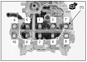
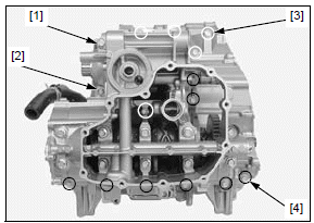
Loosen the following in a crisscross pattern in 2 or 3 steps:
- 10 mm bolt [1]
- 8 mm bolt [2]
- Five 6 x 50 mm bolts [3]
- Eight 6 x 35 mm bolts [4]
Remove the all bolts.
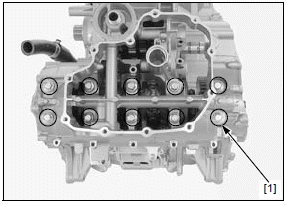
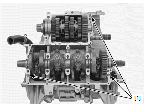
Loosen the crankcase main journal bolt [1] in a crisscross pattern in 2 or 3 steps, and remove them.
Do not pry the crankcase halves with a screwdriver.
Separate the lower crankcase from the upper crankcase.
Remove the dowel pins [1] and oil orifices [2].
ASSEMBLY
Clean the upper and lower crankcase mating surfaces thoroughly, being careful not to damage them.
Check the crankcase oil passages for clogs, and clean them if necessary.
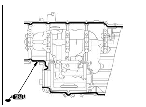
Apply sealant (TB1207B manufactured by ThreeBond or an equivalent) to the crankcase mating surface as shown.
NOTE:
- Do not apply liquid sealant more than necessary.
- Do not apply liquid sealant to the crankcase main journal bolts area and the oil passage area.
Clean the oil orifices in solvent thoroughly.
Check the oil orifices for clogs, and replace them if necessary.
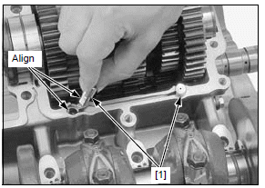
Install the oil orifices [1] by aligning its cut-out with the groove of upper crankcase.
Install the dowel pins [1] into the upper crankcase.
Apply molybdenum oil solution to the main journal bearing sliding surfaces on the lower crankcase.
Install the lower crankcase onto the upper crankcase.
Install new crankcase main journal bolts [1].
NOTE:
- Tighten the crankcase main journal bolts using the Plastic Region Tightening Method.
- Do not reuse the crankcase main journal bolts, because the correct axial tension will not be obtained.
- The crankcase main journal bolts are pre-coated with an oil additive for axial tension stability. Do not remove the oil additive from the new crankcase main journal bolt surfaces.
Make sure the upper and lower crankcase are seated securely.
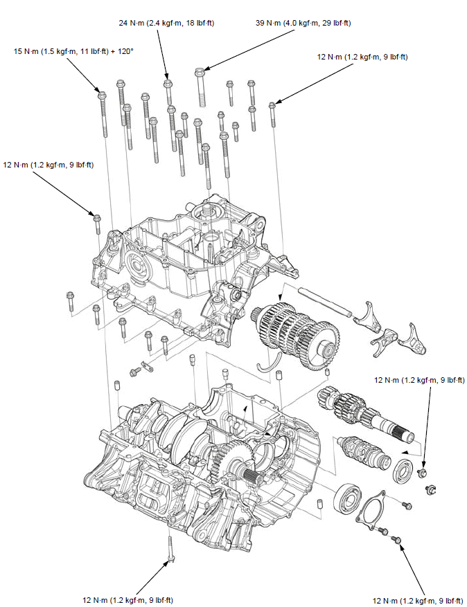
Tighten the crankcase main journal bolts in numerical order as shown in a crisscross pattern in 2 or 3 steps to the specified torque.
Further tighten the crankcase main journal bolts 120º.
TORQUE:15 N*m (1.5 kgf*m, 11 lbf*ft) + 120º
Install the all crankcase bolts.
Tighten the crankcase bolts in a crisscross pattern in 2 or 3 steps to the specified torque.
TORQUE:
Crankcase 10 mm bolt [1]:
39 N*m (4.0 kgf*m, 29 lbf*ft)
Crankcase 8 mm bolt [2]:
24 N*m (2.4 kgf*m, 18 lbf*ft)
Crankcase 6 x 50 mm bolt [3]:
12 N*m (1.2 kgf*m, 9 lbf*ft)
Crankcase 6 x 35 mm bolt [4]
12 N*m (1.2 kgf*m, 9 lbf*ft)
Install the wire stay [1] and bolt [2], then tighten the bolt.
Tighten the crankcase 6 x 50 mm bolt [3] to the specified torque.
TORQUE:12 N*m (1.2 kgf*m, 9 lbf*ft)
Install the removed parts in the reverse order of removal.
See also:
 Honda CBR650 - Service manual > Transmission
REMOVAL Separate the crankcase halves. Remove the countershaft assembly [1] and dowel pin [2].
 Rider's Manual BMW R 1250 GS GSA
 Owner's Manual Harley-Davidson Sportster XL1200X Forty-Eight
 Owner's Manual Honda CBR650R
 Service manual Honda CBR650
 Owner's Manual Honda PCX125
 Owner's Manual Kawasaki Z1000SX
 Service manual Kawasaki Z1000SX
 Owner's Manual Lexmoto Echo
 Owner's Manual Royal Enfield Interceptor 650
 Service manual Royal Enfield Interceptor 650
 Owner's Manual Yamaha MT-07