 Honda CBR650 - Service manual > Transmission
REMOVAL
Separate the crankcase halves.
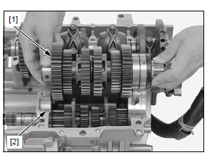
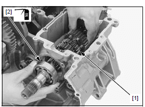
Remove the countershaft assembly [1] and dowel pin [2].
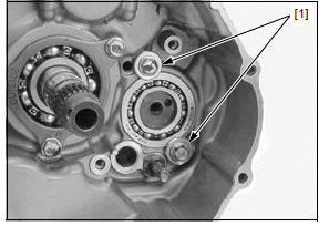
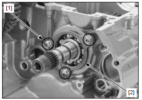
Remove the shift drum bearing setting washer-bolts [1].
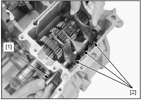
Remove the shift fork shaft [1] and shift forks [2].
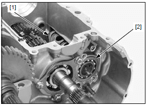
Remove the shift drum [1]/bearing [2] assembly.
Remove the shift drum bearing from the shift drum.
Remove the bolts [1] and mainshaft bearing setting plate [2].
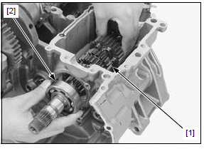
Slide the mainshaft assembly [1] off the upper crankcase and remove the right mainshaft bearing [2].
Remove the mainshaft assembly.
INSPECTION
Inspect the following parts for scratch, damage, abnormal wear and deformation. Replace if necessary.
- Transmission gears
- Transmission bushings
- Transmission bearings
- Shift drum/bearing
- Shift forks
- Shift fork shaft
Measure each part and calculate the clearance according to CRANKCASE/TRANSMISSION SPECIFICATIONS.
Replace any part if it is out of service limit.
MAINSHAFT BEARING REPLACEMENT
Remove the transmission.
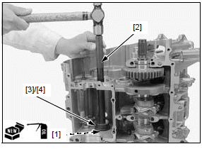
Remove the mainshaft bearing [1] using the special tools as shown.
TOOLS:
[2] Bearing remover set, 20 mm 07936-3710600
[3] Remover weight 07741-0010201
[4] Remover handle 07936-3710100
Drive in a new bearing squarely with the marking side facing down.
Apply engine oil to a new main shaft bearing [1].
Drive a new bearing into the crankcase until it is fully seated using the special tools.
TOOLS:
[2] Driver 07949-3710001
[3] Attachment, 42 x 47 mm 07746-0010300
[4] Pilot, 20 mm 07746-0040500
Install the transmission.
DISASSEMBLY/ASSEMBLY
NOTE:
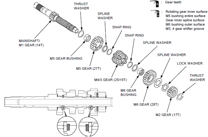
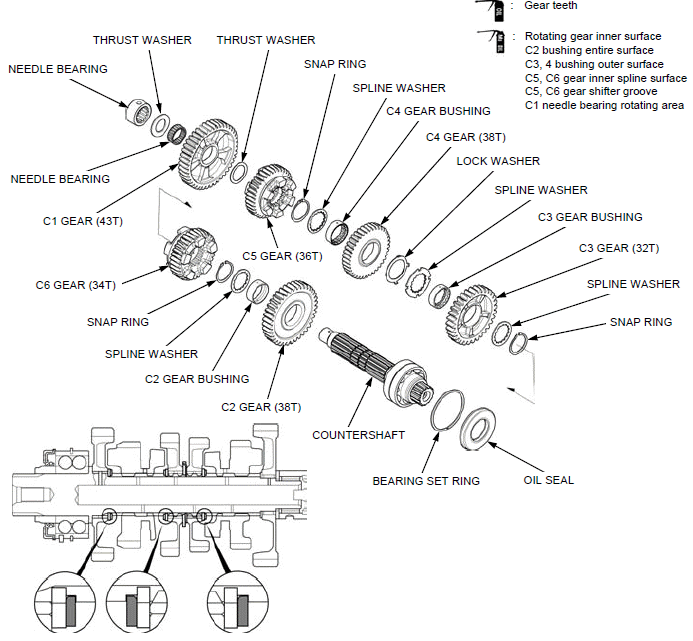
- Coat each gear with clean engine oil and check for smooth movement.
- Align the lock washer tabs with the spline washer grooves.
- Always install the thrust washers and snap rings with the chamfered (rolled) edge facing away from the thrust load.
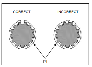
- Install the snap rings [1] so that the end gap aligns with the groove of the splines.
- Make sure that the snap rings are fully seated in the shaft groove after installing them.
MAINSHAFT
COUNTERSHAFT
INSTALLATION
Install the mainshaft assembly [1] into the upper crankcase.
Apply engine oil to the mainshaft bearing [2].
Install the bearing into the crankcase with the marked side facing out.
Install the mainshaft bearing [2] into the upper crankcase.
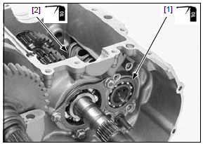
Apply locking agent to the mainshaft bearing setting plate bolts [1] threads.
Install the mainshaft bearing setting plate [2] and setting plate bolts.
Tighten the setting plate bolts to the specified torque.
TORQUE:12 N*m (1.2 kgf*m, 9 lbf*ft)
Apply engine oil to the shift drum bearing [1] and shift drum [2] journal outer surface.
Install the bearing onto the shift drum with the marked side facing out.
Install the shift drum bearing onto the shift drum.
Install the shift drum/bearing assembly into the upper crankcase.
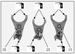
The shift forks have the following identification marks:
- "L" mark [1]: left shift fork
- "C" mark [2]: center shift fork
- "R" mark [3]: right shift fork
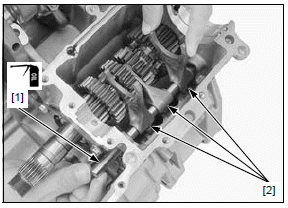
Apply engine oil to the shift fork guide area and guide pin.
Apply engine oil to the shift fork shaft [1] outer surface.
Install the shift forks [2] into the shift drum guide grooves and shifter groove (center shift fork) with the identification marks facing toward the right side of the engine, then insert the fork shaft.
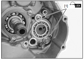
Apply locking agent to the shift drum bearing setting washer-bolt [1] threads.
Install and tighten the shift drum bearing setting washer-bolts to the specified torque.
TORQUE:12 N*m (1.2 kgf*m, 9 lbf*ft)
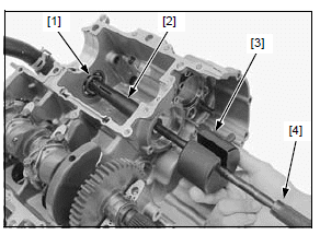
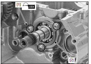
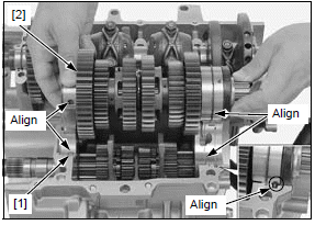
Install the dowel pin [1] onto the upper crankcase hole.
Install the countershaft [2] by aligning the following:
- Set ring with the groove of the upper crankcase
- Bearing cap hole with the dowel pin
- Countershaft bearing stopper pin with the groove of the upper crankcase
Assemble the crankcase halves.
See also:
 Honda CBR650 - Service manual > Service information
GENERAL The crankcase must be separated to service the following: Transmission Crankshaft Piston/connecting rod/cylinder The following components must be removed before separating the crankcase: Engine Clutch Gearshift linkage Starter clutch Flywheel Cylinder head Oil pan Oil pump Oil cooler Starter motor Water pump EOP switch VS sensor Neutral switch Be careful not to damage the crankcase mating surfaces when servicing. Prior to assembling the crankcase halves, apply sealant to their mating surfaces. Wipe off excess sealant thoroughly.
 Rider's Manual BMW R 1250 GS GSA
 Owner's Manual Harley-Davidson Sportster XL1200X Forty-Eight
 Owner's Manual Honda CBR650R
 Service manual Honda CBR650
 Owner's Manual Honda PCX125
 Owner's Manual Kawasaki Z1000SX
 Service manual Kawasaki Z1000SX
 Owner's Manual Lexmoto Echo
 Owner's Manual Royal Enfield Interceptor 650
 Service manual Royal Enfield Interceptor 650
 Owner's Manual Yamaha MT-07