 Royal Enfield Interceptor 650 - Service manual > Stator Assembly with CPS
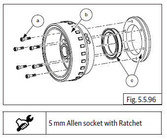
Stator Assembly with Crank Position Sensor (CPS)
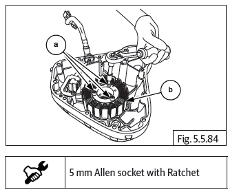
- Loosen and remove 3 Nos. Hex socket head screws (M6) (a) holding the stator assembly (b).
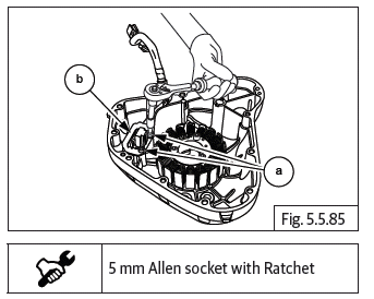
- Loosen and remove 2 Nos. Hex socket head screws (M6) (a) on guide plate (b), holding crank position sensor to magneto cover.
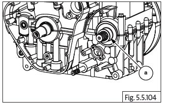
- Remove the guide plate (a) from magneto cover.
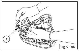
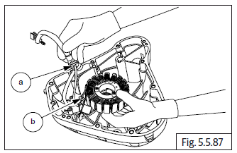
- Gently release the wiring grommet (a) from the magneto cover.
- Gently remove stator assembly (b) from magneto cover.
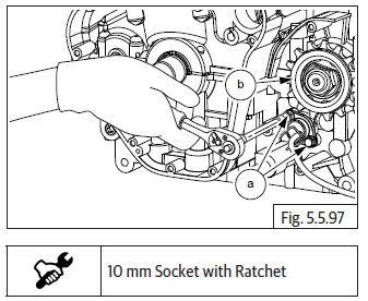
Magneto Rotor Bolt
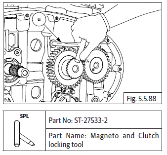
- In order to loosen magneto rotor bolt, it will be necessary to remove clutch cover.
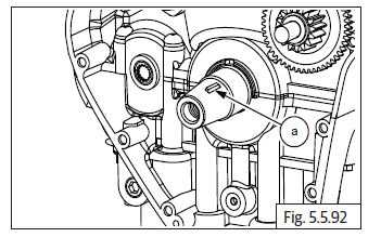
- Insert special tool (a) in crankcase RH to lock the crankshaft and prevent rotation.
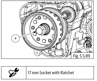
- Loosen and remove Hex flange head bolt (M12) (a).
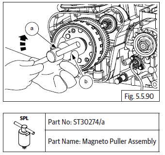
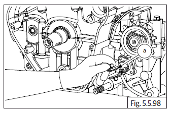
- Ensure center bolt of magneto rotor puller is loosened sufficiently.
- Assemble puller (b) on magneto rotor (a) and thread in fully.
- Tighten center bolt onto puller till magneto rotor gets rreleased from crankshaft.
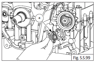
- Gently pull out magneto rotor assembly (a) with starter clutch.
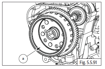
- Remove woodruff key (a) from crankshaft.
Starter Clutch from Magneto Rotor
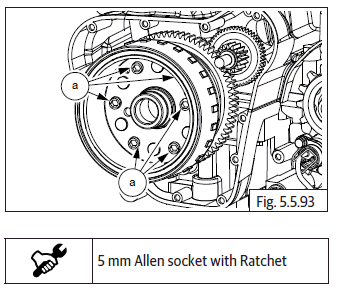
- Slightly loosen 6 Nos. Hex socket head screws (M6) (a) from inside magneto rotor. Do not LOOSEN AND REMOVE FULLY.
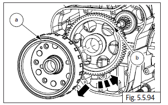
- Remove magneto rotor assembly (a) from crank shaft, hold the rotor firmly, rotate gear starter clutch (b) anti-clockwise and pull out simultaneously to separate rotor from the gear.
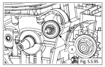
- Remove starter idle gear (a).
- Loosen and remove 6 Nos. Hex socket head screws (M6) (a) from inside magneto rotor (b) and separate starter clutch with outer ring (c).
- Remove starter clutch from outer ring.
Gear Position Sensor
- Loosen and remove 2 Nos. Hex head bolts (M6) (a) along with bracket located below the FD sprocket (b).
- Remove cable holder (a).
- Gently remove gear position sensor (a).
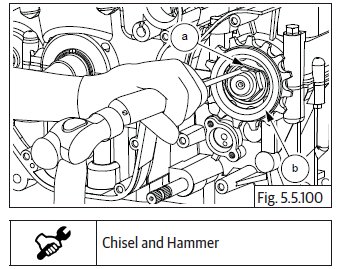
FD Sprocket
- Tap to open lock tab holder (a) located over FD sprocket (b).
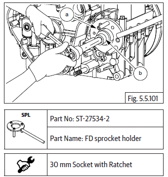
- Locate special tool over FD sprocket (a) and loosen "U" nut (M20) (b).
- Remove lock tab washer (a) from shaft.
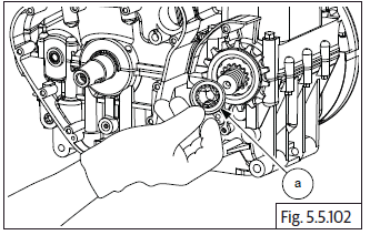
- Remove FD sprocket (a) from drive shaft (b).
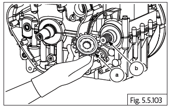
- Gently remove spacer (a) from drive shaft.
CAUTION Do not use sharp tool to remove spacer as it may damage the parts.
See also:
 Royal Enfield Interceptor 650 - Service manual > Rocker Arms from Rocker Carriers LH & RH
Thread in a Hex flange bolt (M6) (a) into the threaded portion of rocker shaft (b). Gently pull out rocker shaft from rocker carrier, duly supporting the rocker arms. Remove rocker arms inlet and exhaust from the rocker carrier. Repeat the procedures above to remove rocker arms from the other carrier. Gently depress the spring (a) and remove from rocker carrierrs (b).
Royal Enfield Interceptor 650 - Service manual > Cylinder Head
Remove oil temperature sensor. CAUTION Cylinder bolts are one time usage only. Always use new head bolts during installation. Dispose old head bolts suitably. Loosen and remove 8 Nos. Hex head bolts (M10) (a) in crisscross pattern on cylinder head. Support cam chain suitably and gently remove cylinder head (a) from cylinder barrel (b). Remove the cylinder head gasket (a) from cylinder barrel (b).
 Rider's Manual BMW R 1250 GS GSA
 Owner's Manual Harley-Davidson Sportster XL1200X Forty-Eight
 Owner's Manual Honda CBR650R
 Service manual Honda CBR650
 Owner's Manual Honda PCX125
 Owner's Manual Kawasaki Z1000SX
 Service manual Kawasaki Z1000SX
 Owner's Manual Lexmoto Echo
 Owner's Manual Royal Enfield Interceptor 650
 Service manual Royal Enfield Interceptor 650
 Owner's Manual Yamaha MT-07