 Royal Enfield Interceptor 650 - Service manual > Center Stand
Chassis / Footrests/Stands/Saree Guard / Center Stand
CAUTION Ensure the motorcycle is upright on a firm and flat surface.
Ensure motorcycle is supported appropriately.
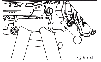
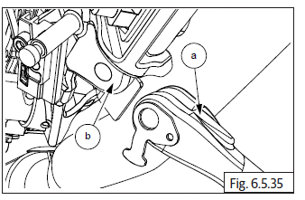
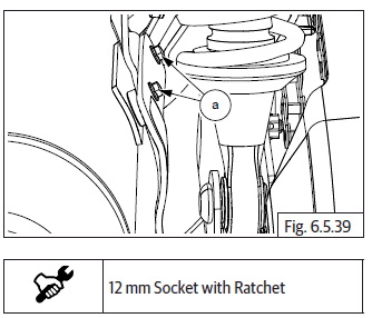
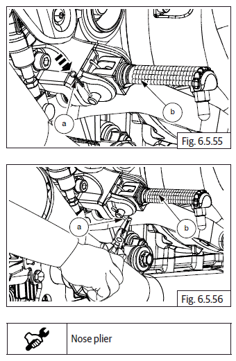
- Locate and support center stand in frame. Insert clevis pin (a) from RH side to assemble center stand to frame.
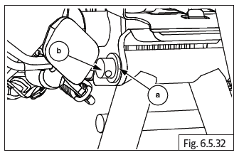
- Install washer (a) into clevis pin (b).
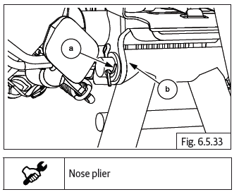
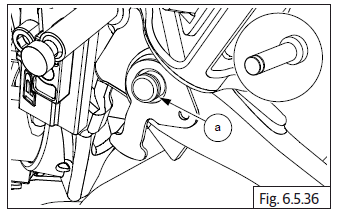
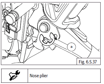
- Install split pin (a) into clevis pin and split the outer end to install center stand (b).
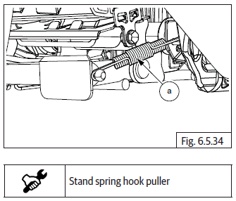
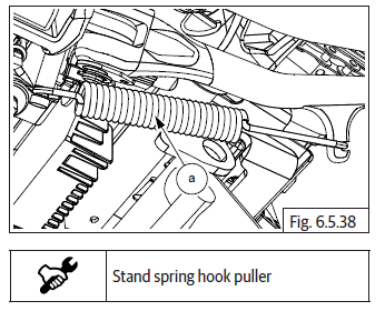
- Install spring (a) into center stand.
Side Stand
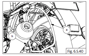
- Locate side stand (a) onto frame (b).
- Insert clevis pin (a) into side stand.
- Install E-clip (a) into clevis pin.
- Install spring (a) into side stand.
Saree Guard (For Indian Market Only)
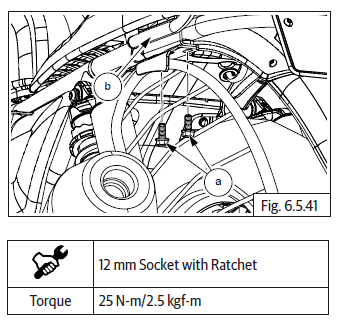
- Locate and tighten 2 Nos. Hex flanged head bolts (M8) (a) into bottom bracket and silencer pipe on LH.
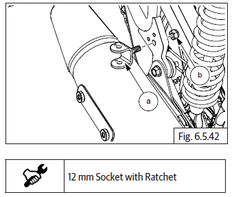
- Gently locate saree guard (a) into bottom bracket (b).
- Ensure rubber bush is seated properly in bottom bracket.
- Locate and tighten 2 Nos. Hex flanged head bolts (M8) (a) into frame and grab handle (b).
Footrest Bracket LH and RH - Pillion
- Position bracket against the frame such that the locking peg in the bracket (a) is located into the hole in frame. Assemble Hex nyloc Nut (M8) (b) from inner side of frame and tighten to specified torque.
Footrests LH and RH - Pillion
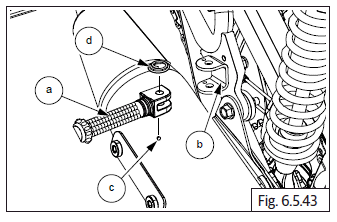
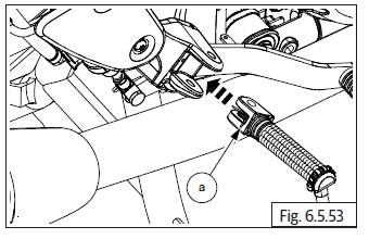
- Apply grease on ball slightly and locate it on the hole in the bracket.
- Insert footrest (a) into mounting bracket (b) with the flat end facing down and taking care not to disturb the seating of ball (c).
- Assemble spring (d) with its conical edge facing upwards within the bracket and footrest.
- Insert clevis pin (a) from footrest housing top, duly supporting footrest (b).
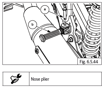
CAUTION Support footrest carefully, since ball and spring loaded.
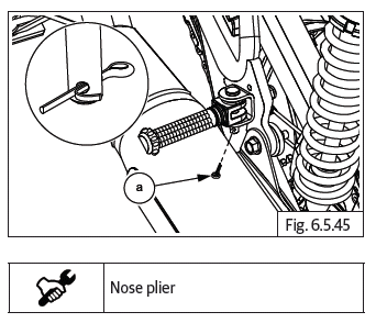
- Insert split pin (a) into clevis pin bottom and expand ends to lock.
Footrest Bracket RH - Rider
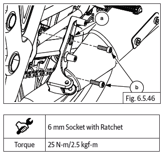
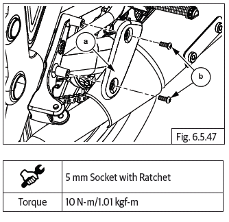
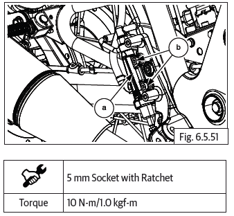
- Locate footrest bracket LH (a) on frame, ensure mounting holes are aligned and tighten with 2 Nos. Hex socket head screws (M8) (b) to specified torque.
- Position heel guard LH (a) against bracket, align mounting holes and tighten with 2 Nos. Hex socket head screws (M6) (b) to specified torque.
Footrest Bracket RH - Rider
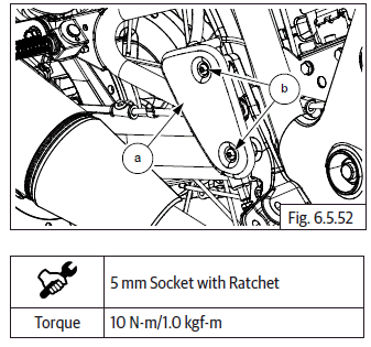
- Gently hold footrest bracket and align mounting hole of brake pedal, insert hex socket bolt (M8) (a) on inner side of bracket and tighten to specified torque.
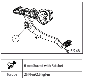
CAUTION Ensure link rod to master cylinder does not get damaged. Ensure free movement of brake pedal after tightening.
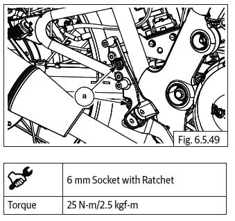
- Align bracket to mounting holes on frame RH, insert 2 Nos. Hex socket head screws (M8) (a) and tighten to specified torque.
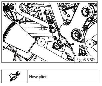
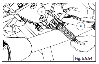
- Assemble spring (a) on footrest bracket (b) and brake pedal.
- Locate master cylinder on footrest bracket (a), ensure mounting holes are aligned. Insert 2 Nos. Hex socket head screws (M6) (b) and tighten to specified torque.
- Position heel guard RH (a) against bracket, align mounting holes and tighten with 2 Nos. Hex socket head screws (M6) (b) to specified torque.
Footrests LH and RH - Rider
- Locate spring into slot in rider footrest such that eyelet is resting on
top. Insert footrest with bracket, duly ensure the following:
- The other end of the spring is located in hole in bracket.
- The flat surface of the peg is facing down.
- Support footrest (a) and spring in bracket, slightly move footrest to align mounting holes.
- Insert clevis pin (a) through top hole in bracket (b), slightly move spring to accommodate clevis pin and push clevis pin completely into the bracket.
- Insert split pin (a) into clevis pin (b) bottom and expand the ends to lock in place.
NOTE
- After assembling rider footrests, ensure the brakes are functioning properly.
See also:
 Royal Enfield Interceptor 650 - Service manual > Footrest Bracket LH and RH - Pillion
Support pillion footrest bracket (a), loosen and remove Hex nyloc nut (M8) (b) from inner side of frame.
Royal Enfield Interceptor 650 - Service manual > Mudguards/Number Plates/Grab Handle
Front Number Plate Front Mudguard
 Rider's Manual BMW R 1250 GS GSA
 Owner's Manual Harley-Davidson Sportster XL1200X Forty-Eight
 Owner's Manual Honda CBR650R
 Service manual Honda CBR650
 Owner's Manual Honda PCX125
 Owner's Manual Kawasaki Z1000SX
 Service manual Kawasaki Z1000SX
 Owner's Manual Lexmoto Echo
 Owner's Manual Royal Enfield Interceptor 650
 Service manual Royal Enfield Interceptor 650
 Owner's Manual Yamaha MT-07