 Kawasaki Z1000SX - Service manual > Stator Coil Installation
- Apply a non-permanent locking agent to the threads of the stator coil
bolts and tighten them.
Torque - Stator Coil Bolts: 12 N*m (1.2 kgf*m, 106 in*lb)
- Secure the alternator lead with a holding plate.
- Apply a non-permanent locking agent to the threads of the plate bolt and
tighten it.
Torque - Alternator Lead Holding Plate Bolt: 12 N*m (1.2 kgf*m, 106 in*lb)
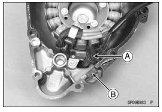
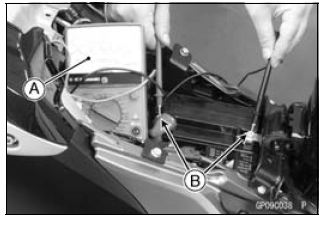
- Apply silicone sealant to the circumference of the alternator lead
grommet [A], and fit the grommet into the notch [B] of the cover securely.
Sealant - Liquid Gasket, TB1211F: 92104-0004
- Install the alternator cover (see Alternator Cover Installation).
Alternator Rotor Removal
- Remove:
Alternator Cover (see Alternator Cover Removal)
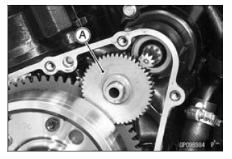
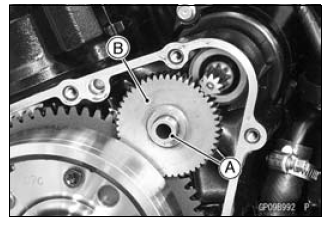
Starter Idle Gear [A]
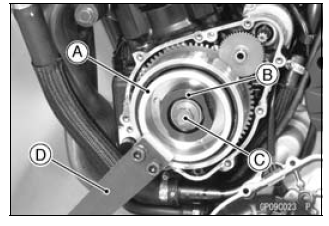
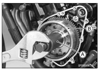
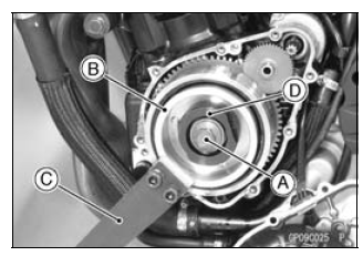
- Hold the alternator rotor steady with the rotor holder [A] and stopper [B].
- Remove the rotor bolt [C] and washer.
Special Tools -
Grip [D]: 57001-1591
Stopper: 57001-1679
Rotor Holder: 57001-1690
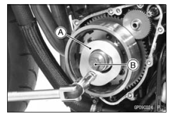
If using the rotor holder (57001-1757).
- Hold the alternator rotor steady with the rotor holder [A].
- Remove the rotor bolt [B] and washer.
Special Tool - Rotor Holder: 57001-1757
- Using the flywheel puller [A], remove the alternator rotor [B] from the
crankshaft.
Special Tool - Flywheel Puller Assembly, M38 × 1.5/M35 × 1.5: 57001-1615
NOTICE Do not attempt to strike the alternator rotor itself.
Striking the rotor can cause the magnets to lose their magnetism.
Alternator Rotor Installation
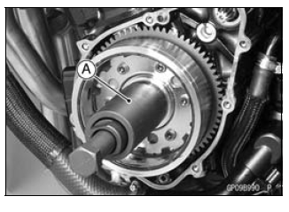
- Apply a thin coat of molybdenum disulfide grease to the crankshaft [A] and the outer surface [B] of the starter clutch gear [C].
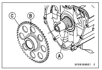
- Install the starter clutch gear [A].
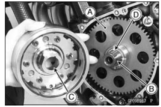
- Using a cleaning fluid, clean off any oil or dirt on the following
portions and dry them with a clean cloth.
Crankshaft Tapered Portion [B]
Alternator Rotor Tapered Portion [C] - Fit the woodruff key [D] securely in the slot in the crankshaft before installing the alternator rotor.
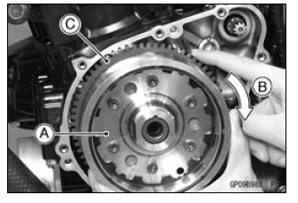
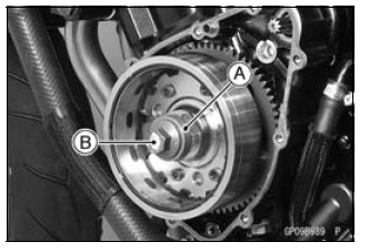
- Install the alternator rotor [A] while turning [B] the starter clutch gear [C] clockwise.
- Using a cleaning fluid, clean off any oil or dirt on the washer [A] and dry it with a clean cloth.
- Install the washer.
NOTE
- Confirm the alternator rotor fit or not to the crankshaft before tightening it with specified torque.
- Install the rotor bolt [B] and tighten it with 70 N*m (7.0 kgf*m, 52 ft*lb) of torque.
- Remove the rotor bolt and washer.
- Check the tightening torque with flywheel puller [A].
Special Tool - Flywheel Puller Assembly, M38 × 1.5/M35 × 1.5: 57001-1615
If the rotor is not pulled out with 20 N*m (2.0 kgf*m, 15 ft*lb) of drawing torque, it is installed correctly.
If the rotor is pulled out with under 20 N*m (2.0 kgf*m, 15 ft*lb) of drawing torque, clean off any oil dirt or flaw of the crankshaft and rotor tapered portion, and dry them with a clean cloth. Then, confirm that it is not pulled out with above torque.
- Install the washer and rotor bolt.
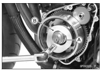
- Tighten the alternator rotor bolt [A] while holding the alternator rotor
steadily with the holder [B].
Special Tools -
Grip [C]: 57001-1591
Rotor Holder: 57001-1690
Stopper [D]: 57001-1679
Torque - Alternator Rotor Bolt: 155 N*m (15.8 kgf*m, 114 ft*lb)
If using rotor holder (57001-1757).
- Install the washer and rotor bolt.
- Tighten the alternator rotor bolt [A] while holding the alternator rotor steadily with the holder [B].
Special Tool - Rotor Holder: 57001-1757
Torque - Alternator Rotor Bolt: 155 N*m (15.8 kgf*m, 114 ft*lb)
- Apply a thin coat of molybdenum disulfide grease to the shaft [A], and install it and starter idle gear [B].
- Install the alternator cover (see Alternator Cover Installation).
Alternator Inspection
There are three types of alternator failures: short, open (wire burned out), or loss in rotor magnetism. A short or open in one of the coil wires will result in either a low output, or no output at all. A loss in rotor magnetism, which may be caused by dropping or hitting the alternator, by leaving it near an electromagnetic field, or just by aging, will result in low output.
- To check the alternator output voltage, do the following procedures.
- Turn off the ignition switch.
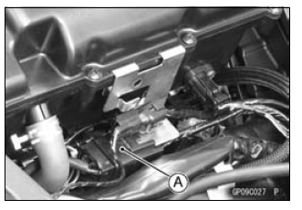
- Disconnect the alternator lead connector [A] (see alternator Cover Removal).
- Connect the hand tester as shown in the table 1.
- Start the engine.
- Run it at the rpm given in the table 1.
- Note the voltage readings (total 3 measurements).
Table 1 Alternator Output Voltage
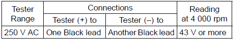
If the output voltage shows the value in the table, the alternator operates properly.
If the output voltage shows a much higher than the value in the table, the regulator/rectifier is damaged. A much lower reading than that given in the table indicates that the alternator is defective.
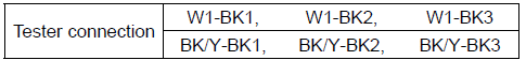
- Check the stator coil resistance as follows.
- Stop the engine.
- Connect the hand tester as shown in the table 2.
- Note the readings (total 3 measurement).
Table 2 Stator Coil Resistance at 20ºC (68ºF)
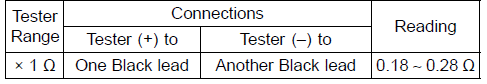
If there is more resistance than shown in the table, or no hand tester reading (infinity) for any two leads, the stator has an open lead and must be replaced. Much less than this resistance means the stator is shorted, and must be replaced.
- Using the highest resistance range of the hand tester, measure the resistance between each of the black leads and chassis ground.
Any hand tester reading less than infinity (∞) indicates a short, necessitating stator replacement.
If the stator coils have normal resistance, but the voltage check showed the alternator to be defective; then the rotor magnets have probably weakened, and the rotor must be replaced.
Special Tool - Hand Tester: 57001-1394
Regulator/Rectifier Inspection
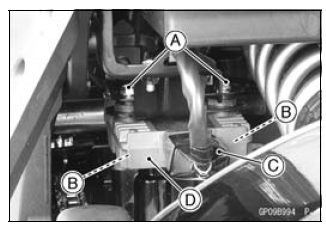
ZX1000G Model
- Remove:
Bolts [A] and Nuts [B]
Connector [C] (Disconnect)
Regulator/Rectifier [D]
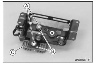
ZX1000H Model
- Remove:
ABS Hydraulic Unit (see ABS Hydraulic Unit Removal in the Brakes chapter)
Bolts [A] and Nuts [B]
Regulator/Rectifier [C]
Rectifier Circuit Check
- Check conductivity of the following pair of terminals.
Rectifier Circuit Inspection
The resistance should be low in one direction and more than ten times as much in the other direction. If any two terminals are low or high in both directions, the rectifier is defective and the regulator/rectifier must be replaced.
NOTE
- The actual meter reading varies with the meter used and the individual rectifier, but, generally speaking the lower reading should be from zero to one half the scale.
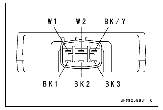
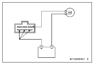
Regulator Circuit Check
To test the regulator out of circuit, use three 12 V batteries and a test light (12 V 3 - 6 W bulb in a socket with leads).
NOTICE The test light works as an indicator and also a current limiter to protect the regulator/rectifier from excessive current. Do not use an ammeter instead of a test light.
- Check to be sure the rectifier circuit is normal before continuing.
- Do the 1st step regulator circuit test.
- Connect the test light and the 12 V battery to the regulator/ rectifier as shown in the figure.
- Check the BK1, BK2 and BK3 terminal respectively.
If the test light turns on, the regulator/rectifier is defective.
Replace it.
If the test light does not turn on, continue the test.
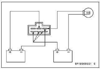
- Do the 2nd step regulator circuit test.
- Connect the test light and the 12 V battery in the same manner as specified in the "Regulator Circuit Test-1st Step".
- Apply 12 V to the W2 terminal.
- Check the BK1, BK2 and BK3 terminal respectively.
If the test light turns on, the regulator/rectifier is defective.
Replace it.
If the test light does not turn on, continue the test.
- Do the 3rd step regulator circuit test.
- Connect the test light and the 12 V battery in the same manner as specified in the "Regulator Circuit Test-1st Step".
- Momentarily apply 24 V to the W2 terminal by adding a 12 V battery.
- Check the BK1, BK2 and BK3 terminals respectively.
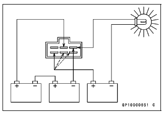
NOTICE Do not apply more than 24 V. If more than 24 V is applied, the regulator/rectifier may be damaged. Do not apply 24 V more than a few seconds. If 24 V is applied for more than a few seconds, the regulator/ rectifier may be damaged.
If the test light did not light when the 24 V was applied momentarily to the voltage monitoring terminal, the regulator/ rectifier is defective. Replace it.
If the regulator/rectifier passes all of the tests described, it may still be defective. If the charging system still does not work properly after checking all of the components and the battery, test the regulator/rectifier by replacing it with a known good unit.
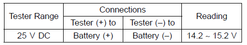
Charging Voltage Inspection
- Check the battery condition (see Charging Condition Inspection).
- Warm up the engine to obtain actual alternator operating conditions.
- Check that the ignition switch is turned off, and connect the hand
tester [A] to the battery terminals [B].
Special Tool - Hand Tester: 57001-1394
- Start the engine, and note the voltage readings at various engine speeds with the headlight turned on and then turned off (To turn off the headlight, disconnect the headlight connector on the headlight unit.). The readings should show nearly battery voltage when the engine speed is low, and, as the engine speed rises, the readings should also rise. But they must be kept under the specified voltage.
Charging Voltage
- Turn off the ignition switch to stop the engine, and disconnect the hand
tester.
If the charging voltage is kept between the values given in the table, the charging system is considered to be working normally.
If the charging voltage is much higher than the values specified in the table, the regulator/rectifier is defective or the regulator/rectifier leads are loose or open.
If the charging voltage does not rise as the engine speed increases, then the regulator/rectifier is defective or the alternator output is insufficient for the loads. Check the alternator and regulator/rectifier to determine which part is defective.
Charging System Circuit
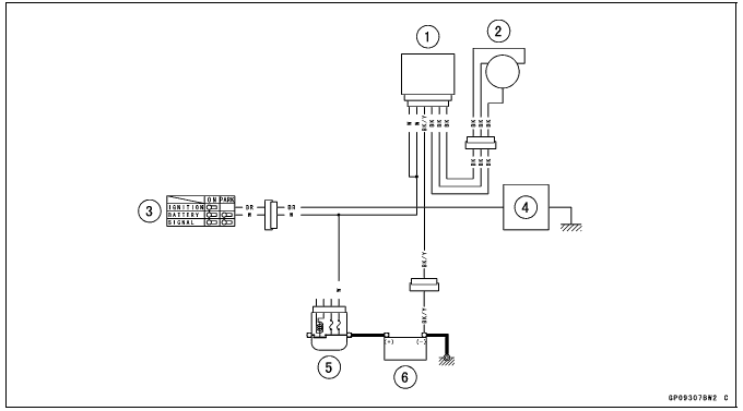
- Regulator/Rectifier
- Alternator
- Ignition Switch
- Load
- Main Fuse 30 A
- Battery 12 V 8 Ah
See also:
 Kawasaki Z1000SX - Service manual > Alternator Cover Removal
Remove: Left Lower Fairing (see Lower Fairing Removal in the Frame chapter) Support the fuel tank with a suitable bar (see Fuel Tank Removal in the Fuel System (DFI) chapter). Pull up the connector bracket [A]. Remove the alternator lead connector [B] from the bracket. Disconnect the alternator lead connector. Place a suitable container under the alternator cover [A]. Remove: Alternator Cover Bolts [B] Bracket [C] Alternator Cover
Kawasaki Z1000SX - Service manual > Ignition System
WARNING The ignition system produces extremely high voltage. Do not touch the spark plug, ignition coil or ignition coil lead while the engine is running, or you could receive a severe electrical shock.
 Rider's Manual BMW R 1250 GS GSA
 Owner's Manual Harley-Davidson Sportster XL1200X Forty-Eight
 Owner's Manual Honda CBR650R
 Service manual Honda CBR650
 Owner's Manual Honda PCX125
 Owner's Manual Kawasaki Z1000SX
 Service manual Kawasaki Z1000SX
 Owner's Manual Lexmoto Echo
 Owner's Manual Royal Enfield Interceptor 650
 Service manual Royal Enfield Interceptor 650
 Owner's Manual Yamaha MT-07